Triacs Information
Last revised: September 18, 2024
Reviewed by: Scott Orlosky, consulting engineer
 Triacs are three-terminal silicon devices that are configured in an inverse parallel arrangement to provide load current during both halves of the AC supply voltage. They have two anodes (A1 and A2) for conducting current in both directions.
They also have two gates (G1 and G2), each of which triggers a corresponding anode. As a rule, the gate trigger voltage is the same polarity as the voltage through the triac. For example, if the voltage from A1 to A2 is positive, then the gate trigger voltage is also positive.
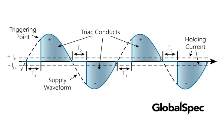
Once triggered, triacs continue to conduct current as long as there is current flow, even if there is no longer voltage at the gate terminal.
Typically, triacs are used to control motor speed. Because load current (armature speed) flows during both halves of the applied AC voltage, motors rotate smoothly at all rotational speeds.
A triac is essentially two Silicon Controlled Rectifiers (SCRs) connected in parallel but in opposite directions, with their gate inputs tied together. This configuration allows the triac to conduct current in both directions when triggered.
In its initial state, the triac acts as an open circuit between the AC supply and the load (e.g., a lamp). No current flows through the triac until it is triggered.
The triac is triggered when a minimum gate current is either sourced or sunk through the gate pin. This gate current causes the triac to latch on, allowing current to flow through it.
Once triggered, the triac latches on and continues to conduct current until the current flowing through it goes to zero. This typically happens at the next zero crossing of the AC waveform, where the AC voltage naturally passes through zero.
At the zero crossing point of the AC waveform, the current through the triac drops to zero. If no gate current is applied at this point, the triac will turn off and return to its open circuit state.
The two main terminals of the triac are not completely interchangeable. The bias current for the triac depends, to an extent, on the direction of the bias current. This means that the behavior of the triac can vary slightly depending on the direction of the AC current
This operation makes triacs particularly useful in AC power control applications such as light dimmers, motor speed controls, and other devices that require switching and phase control of AC signals.
Types
Standard or four-quadrant (4Q) triacs can be triggered in all four modes. 4Q triacs must include additional protection components such as resistor-capacitor (RC) snubbers across the main terminals and an inductor that is in series with the device.
Three-quadrant (3Q) triacs can be triggered in only quadrants 1, 2, and 3. Because they do not require protection circuitry, 3Q devices are more efficient than standard triacs in applications with non-resistive loads.
Snubbers are circuits that limit the voltage and the rising ratio of off-state voltage during device turn-off. They also limit the critical current rate-of-rise during device turn-on.
Specifications
Selecting triacs requires an analysis of performance specifications.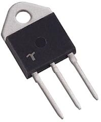
Peak repetitive off-state voltage is the maximum instantaneous value of the off-state voltage that occurs across a triac, including all repetitive transient voltages.
Peak repetitive reverse voltage is the maximum reverse voltage that may be applied continuously to the anode and cathode.
Peak cycle surge on-current is the maximum on-state current of short-term duration that can be applied for one full cycle of conduction without performance degradation.
Gate trigger current is the minimum current required to switch triacs from the off-state to the on-state at the specified off-state voltage and temperature.
Gate trigger voltage is the voltage required to produce the gate trigger current.
Root mean square (RMS) on-state current is the maximum RMS value of the principal current when devices are turned on.
Rising ratio of off-voltage is the minimum rate-of-rise value for the principal voltage that causes switching from the off-state to the on-state.
Other performance specifications include:
- Repetitive peak controllable on-state voltage
- Rate-of-rise off-state voltage
- Critical current rate-of-rise
- Power dissipation
- Operating temperature
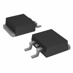
Integrated Circuit (IC) Package Types
Triacs are available in a variety of integrated circuit (IC) packages and with different number of pins. Basic IC package types include
- Dual in-line package (DIP)
- Diode outline (DO)
- Transistor outline (TO)
- Small outline diode (SOD)
- Small outline transistor (SOT)
DIPs are available in either ceramic (CDIP) or plastic (PDIP).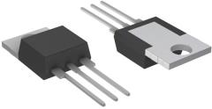
IC package types for silicon controlled rectifiers include discrete packaging (DPAK), integrated packaging (IPAK), power packaging (PPAK), and metal electrode leadless face (MELF).
D2PAK is large surface mounted package that includes a heat sink.
I2PAK is a plastic package with three leads.
Thin small outline package (TSOP), a type of DRAM package that uses gull wing shaped leads on both sides, is available with both L-shaped leads (TSSOP) and J-shaped leads (TSOJ).
Triacs FAQs
What is the difference between the main terminals of a Triac?
The main terminals of a Triac, commonly referred to as MT1 and MT2, have specific roles and characteristics that differentiate them. The Triac operates in four conduction quadrants, which are defined by the direction of current flow through the main terminals and the gate. These quadrants are as follows.
- Quadrant I: Current flows into MT2 and out of MT1, with a positive current flow into the gate.
- Quadrant II: Current flows into MT2 and out of MT1, with a negative current flow out of the gate.
- Quadrant III: Current flows into MT1 and out of MT2, with a negative current flow out of the gate.
- Quadrant IV: Current flows into MT1 and out of MT2, with a positive current flow into the gate.
The minimum gate current required for operation varies across these quadrants, with Quadrant IV typically requiring a higher gate current than Quadrants I through III.
The gate sensitivity of a Triac is most optimal in Quadrants I and III, where the gate supply is synchronized with the main terminal supply (gate positive when MT2 is positive, and gate negative when MT2 is negative). Quadrant II is approximately equal in gate sensitivity to Quadrant I, but it has the lowest latching current sensitivity, making it difficult for the triac to latch on when the main terminal current is very low.
How does a triac operate?
A triac remains an open circuit between the AC supply and the load until the minimum gate current is either sourced or sunk through the gate pin. Once triggered, the Triac latches on and continues to conduct until the current through the device goes to zero at the next zero crossing of the AC waveform.
What is the significance of snubbers in triac circuits?
Snubbers play a crucial role in triac circuits, ensuring the reliable and safe operation of the triac. Here are the key points regarding their significance:
Snubbers are designed to limit the voltage across the triac during turn-off. This is important because excessive voltage can cause the triac to switch back on unintentionally, leading to malfunction or damage.
Snubbers also control the rate at which the off-state voltage rises. A rapid rise in voltage can lead to false triggering of the triac. By controlling this rate, snubbers help maintain stable operation.
During turn-on, snubbers limit the critical current rate-of-rise. This is essential to prevent damage to the triac due to sudden surges in current, which can occur when the device switches on.
Snubbers protect the triac from voltage spikes that can occur in the circuit. These spikes can be caused by various factors, such as inductive loads, and can lead to premature failure of the triac if not properly managed.
By managing voltage and current characteristics during switching, snubbers ensure the triac operates reliably over its intended lifespan. This is particularly important in applications where consistent performance is critical, such as in light dimmers and motor speed controls.
Triacs Media Gallery
References
Electronics360— APEC 2024: How to improve switching in solid-state relays
Microchip – Dimming AC Incandescent Lamps Using A PIC10F200 (PDF)
Littelfuse – Fundamental Characteristics of Thyristors (PDF)
Image Credits: