Silicon Controlled Rectifiers (SCR) Information
Last revised: December 10, 2024
Reviewed by: Scott Orlosky consulting engineer
Components
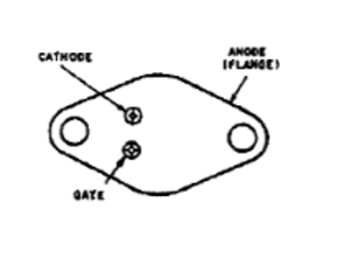
Silicon controlled rectifiers (SCR) are four-layer (PNPN) thyristors with three terminals:
- An input control terminal (gate)
- An output terminal (anode)
- A terminal common to both the input and output (cathode)
Function
SCRs are used mainly with high voltages and currents, often to control alternating current (AC) where the change of sign causes the device to switch off automatically. For example, SCRs are used in dimmer switches where the turn-on point occurs at a specific point on the sine curve of the AC supply. The device then remains on for the remainder of that cycle.
In devices where the gate is left-floating or disconnected, silicon controlled rectifiers behave like Shockley diodes.
Latching is achieved by reaching a breakover voltage or exceeding the critical rate of voltage rise between the anode and cathode.
Dropout is achieved by reducing the current until one or both internal transistors fall into cutoff mode.
Although SCRs offer faster switching speeds than diodes, both types of devices can conduct in only one direction.
Selection Criteria
Selecting silicon controlled rectifiers (SCRs) requires an analysis of performance specifications.
Peak repetitive reverse voltage is the maximum reverse voltage that may be applied continuously to the anode and cathode.
Root mean square (RMS) on-state current is the maximum RMS value of the principal current when SCRs are turned on.
Peak cycle surge on-current is the maximum on-state current of short-term duration that can be applied for one full cycle of conduction without performance degradation.
Gate trigger current is the minimum current required to switch silicon controlled rectifiers from the off-state to the on-state at the specified off-state voltage and temperature.
Gate trigger voltage is the gate voltage required to produce the gate trigger current.
Holding current is the minimum principal current required to maintain SCRs in the on-state.
Rate-of-rise of off-state voltage is the minimum rate-of-rise value for the principal voltage that causes switching from the off-state to the on-state.
Other performance specifications include:
- Repetitive peak controllable on-state voltage
- Temperature junction
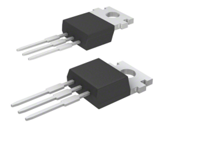
Integrated Circuit (IC) Packages
Silicon controlled rectifiers are available in a variety of integrated circuit (IC) packages and with different number of pins.
Basic IC package types include:
- Dual in-line package (DIP)
- Diode outline (DO)
- Transistor outline (TO)
- Small outline diode (SOD)
- Small outline transistor (SOT)
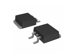
Many packaging variants are available:
- Ceramic (CDIP)
- Plastic (PDIP)
- Discrete packaging (DPAK) — large surface mounted package that includes a heat sink
- Integrated packaging (IPAK) — plastic package with three leads
- Power packaging (PPAK)
- Metal electrode leadless face (MELF)
- Thin small outline package (TSOP) — type of DRAM package that uses gull wing shaped leads on both sides, is available with both L-shaped leads (TSSOP) and J-shaped leads (TSOJ)
Standards
MIL-PRF-19500/108 — Semiconductor device, thyristors (controlled rectifiers), silicon
DSCC-DWG-03021 — Semiconductor device, diode, silicon, rectifier, module, high voltage
Silicon Controlled Rectifiers FAQs
What are the main applications of SCRs?
SCRs are used in various applications, including:
- Capacitor Discharge Ignition (CDI) systems in motorcycles and small engines
- Inrush Current Limiters for bulk capacitors in AC-DC systems
- Line AC Rectifier Bridges for LED lighting systems and battery chargers
- Soft Starters for AC motors
What are the modes of operation for SCR controllers?
SCR controllers typically have two modes of operation:
- Phase Angle Mode: The controller allows a partial waveform to pass through during each half-wave cycle, controlling the power output.
- Zero-Crossing Mode: The controller detects the zero crossing of the AC voltage and allows the controller to start with a zero crossing of the voltage, eliminating harmonic problems often associated with phase angle control.
How are SCRs used in AC circuits?
SCRs are a common means to control alternating current (AC). In phase angle mode, the SCR controller is used to control power by allowing a partial waveform to pass through during each half-wave cycle. This can be used as a dimmer control for lights as an example.
In zero-crossing mode, the SCR controller detects the zero crossing of the AC voltage and allows the controller to start with a zero crossing of the voltage, eliminating harmonic problems often associated with phase angle control.
What are the key benefits of high-temperature SCR switching thyristors?
High-temperature SCR switching thyristors offer several key benefits, particularly in demanding applications where high currents and voltages are involved.
High Junction Temperature
Wider Operating Margin: The high junction temperature of 150 degrees Celsius provides a wider operating margin in existing designs.
Smaller Heat Sinks: This allows the use of smaller heat sinks in new designs, which can reduce the overall size and cost of the system.
Wide Package Selection
Optimal Package Selection: A wide range of package options allows designers the flexibility to select options for their specific application.
Robust Clip-Attach Package Design
High Surge Capability: The robust clip-attach package design enables SCRs to tolerate high onrush currents.
Longer Field Life: This design also resists harsher operating conditions, contributing to a longer field life.
How do zero-crossing SCR controllers eliminate harmonic problems?
The zero-crossing SCR controller detects the zero crossing of the AC voltage: the point where the AC voltage waveform crosses the zero-voltage line. This is the transition from positive to negative or vice versa.
Zero-crossing SCR controllers can synchronize the switching of the SCR with the zero crossing points of an AC voltage waveform.
By allowing the SCR to start conducting precisely at the zero crossing point, the controller ensures that the switching occurs when the voltage is at its minimum. This minimizes abrupt changes in current that typically generate harmonics.
The smooth transition at zero crossing reduces the generation of high-frequency harmonics, which are often associated with phase angle control.
Elimination of Harmonic Problems: The zero-crossing mode effectively eliminates harmonic problems associated with phase angle control. Phase angle control allows a partial waveform to pass through during each half-wave cycle, which can produce significant harmonic distortion.
What are the differences between phase angle control and zero-crossing control in SCR controllers?
Here are the key differences between phase angle control and zero-crossing control in SCR controllers:
Phase Angle Control
Operation: The turn-on point is controlled to occur at a specific point on the AC sine wave.
Power Output Control: This provides precise power control by adjusting the conduction angle of the SCR.
Harmonics: Phase angle control can introduce significant harmonic distortion since the SCR is turned on at various points along the AC waveform causing abrupt changes in current.
Zero-Crossing Control
Operation. The SCR is allowed to start conducting precisely at the zero crossing point, where the voltage is at its minimum.
Harmonic Reduction: This method leads to a smoother transition and minimizes high-frequency harmonics.
Power Quality: Zero-crossing control enhances the overall power quality by eliminating the harmonics.
What are the advantages and limitations of SCRs in AC circuits?
SCRs can handle high currents and voltages, making them suitable for heavy-duty applications such as motor drives, welders, and industrial furnaces.
SCRs allow for precise control of power output. In phase angle control mode, the SCR controller adjusts the conduction angle to control the power output, which is useful in applications like dimmer switches for lights.
SCRs have a robust clip-attach package design that enables high surge capability, allowing them to tolerate high inrush currents and operate under harsher conditions for a longer field life.
Zero-crossing SCR controllers minimize harmonic generation by switching at the zero crossing points of the AC voltage waveform. This method reduces high-frequency harmonics and enhances overall power quality.
High-temperature SCR switching thyristors can operate at junction temperatures up to 150 degrees Celsius, providing a wider operating margin and allowing the use of smaller heat sinks in new designs.
SCRs only conduct in one direction, similar to diodes. This can be a drawback in applications that require bidirectional current flow.
Implementing precise control mechanisms, such as phase angle or zero-crossing control, can add complexity to the design and require additional components and circuitry.
Silicon Controlled Rectifiers Media Gallery
References
GlobalSpec—Power Electronics Design: A Practitioner's Guide
Image Credits:
New Jersey Semi-Conductor Products, Inc. | Digi-Key Corporation