 To some, motor speed control is somewhat of a mystical science, a science
that causes motors and machines to sometimes operate in unexpected
ways. Over 30 years ago, AC drives were considered "new technology." If
a company wanted to have reliable production, it should stick with
known, proven technology - that of DC drives and motors. In many cases,
the cost of transferring manufacturing machinery to AC technology,
would not warrant the lengthy paybacks. It seemed that AC technology
had a long way to go, to improve in reliability and reduced cost. In some
technician's minds, you would need to have a new, back-up AC drive,
because the first one would probably fail upon start-up.
To some, motor speed control is somewhat of a mystical science, a science
that causes motors and machines to sometimes operate in unexpected
ways. Over 30 years ago, AC drives were considered "new technology." If
a company wanted to have reliable production, it should stick with
known, proven technology - that of DC drives and motors. In many cases,
the cost of transferring manufacturing machinery to AC technology,
would not warrant the lengthy paybacks. It seemed that AC technology
had a long way to go, to improve in reliability and reduced cost. In some
technician's minds, you would need to have a new, back-up AC drive,
because the first one would probably fail upon start-up.
As time marched on, low horsepower AC technology improved to the point where total installed costs, including the motor, were equal to - or even less expensive than the DC alternative. The size of the AC drive was equal to or smaller that its DC counterpart. Improvements in power electronics increased the reliability of AC drives, to the point where one would almost never hear of a drive failure upon start-up.
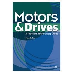
This book is intended to de-mystify drive and motor technology, used in today's modern manufacturing processes. The text has roots in the practical side of drive and motor use, with the "design engineering" side of technology, presented in commonly used terms. An attempt is made to help the reader "start from scratch," gathering and reviewing a collection of basic information - from basic electrical principles to DC and AC motor principles of operation. The initial cost of a motor only represents about 3% of its total lifetime expense, with operating costs representing the other 97%. Therefore, energy savings with VFDs (variable frequency drives) is a topic that faces many consumers in this day of rising energy costs.
From the basics, the reader is lead on a historical path - reviewing DC and AC drives that are 10 years old or more. The focus of this section however, points to the new and improved technology, in both types of drives.
From that point, the reader is lead into feedback methods and devices, and into closed loop control of drive systems. The concepts reviewed, are the basics of modern industrial and commercial HVAC systems.
An overall attempt is made to start with the basics, and move into the more complex concepts of drive operation and design. The book also compares the two technologies, AC and DC, and provides questions and issues to review when making any drive technology decision. The book ends with general principles of drive troubleshooting, and ideas on how to conduct routine drive maintenance.
Summary sections and "Test your Knowledge" questions are provided at the end of each chapter, to assist in confirming important points. In addition, the Appendices are offered as a reference section, providing terms and definitions, as well as formulas, conversions and enclosure information.
Many types of drives are on the market today - ranging from the size of a person's fist - to 14 bay cabinets, with the electronics to power thousands of motor horsepower. Open loop (V/Hz) AC drives are the most common drive in use today, with up to 70% use, according to some surveys. Behind the standard open loop drive, stands several other types of drive products: brush DC servo drives, DC drives, SCR DC drives, stepper drives / motors, AC servo drives, and brushless DC servo drives. Though in smaller percentage of use, encoderless flux vector, closed loop vector, and direct torque control type drives are gaining in popularity.
It is hoped that this book can be used as a resource for those that design, apply or maintain AC or DC motor speed controls. It is meant to be an overall "book of knowledge" on a student's, technician's or engineer's bookshelf.
 TABLE OF CONTENTS