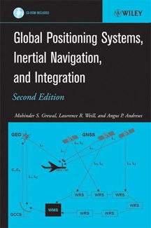
This book is intended for people who need to combine global navigation satellite systems (GNSSs), inertial navigation systems (INSs), and Kalman filters. Our objective is to give our readers a working familiarity with both the theoretical and practical aspects of these subjects. For that purpose we have included "realworld" problems from practice as illustrative examples. We also cover the more practical aspects of implementation: how to represent problems in a mathematical model, analyze performance as a function of model parameters, implement the mechanization equations in numerically stable algorithms, assess its computational requirements, test the validity of results, and monitor performance in operation with sensor data from GNSS and INS. These important attributes, often overlooked in theoretical treatments, are essential for effective application of theory to real-world problems.
The accompanying CD-ROM contains MATLAB m-files to demonstrate the workings of the Kalman filter algorithms with GNSS and INS data sets, so that the reader can better discover how the Kalman filter works by observing it in action with GNSS and INS. The implementation of GNSS, INS, and Kalman filtering on computers also illuminates some of the practical considerations of finite-wordlength arithmetic and the need for alternative algorithms to preserve the accuracy of the results. Students who wish to apply what they learn, must experience all the workings and failings of Kalman Filtering and learn to recognize the differences.
The book is organized for use as a text for an introductory course in GNSS technology at the senior level or as a first-year graduate-level course in GNSS, INS, and Kalman filtering theory and application. It could also be used for selfinstruction or review by practicing engineers and scientists in these fields.
This second edition includes some significant changes in GNSS/INS technology since 2001, and we have taken advantage of this opportunity to incorporate many of the improvements suggested by reviewers and readers. Changes in this second edition include the following:
- New signal structures for GPS, GLONASS, and Galileo
- New developments in augmentation systems for satellite navigation, including
(a) Wide-area differential GPS (WADGPS)
(b) Local-area differential GPS (LADGPS)
(c) Space-based augmentation systems (SBASs) (d) Ground-based augmentation systems (GBASs) - Recent improvements in multipath mitigation techniques, and new clock steering algorithms
- A new chapter on satellite system integrity monitoring
- More thorough coverage of INS technology, including development of error models and simulations in MATLAB for demonstrating system performance
- A new chapter on GNSS/INS integration, including MATLAB simulations of different levels of tight/loose coupling
The CD-ROM enclosed with the second edition has given us the opportunity to incorporate more background material as files. The chapters have been reorganized to incorporate the new material.
Chapter 1 informally introduces the general subject matter through its history of development and application. Chapters 2-7 cover the basic theory of GNSS and present material for a senior-level class in geomatics, electrical engineering, systems engineering, and computer science.
Chapters 8-10 cover GNSS and INS integration using Kalman filtering. These chapters could be covered in a graduate-level course in electrical, computer, and systems engineering. Chapter 8 gives the basics of Kalman filtering: linear optimal filters, predictors, nonlinear estimation by "extended" Kalman filters, and algorithms for MATLAB implementation. Applications of these techniques to the identification of unknown parameters of systems are given as examples. Chapter 9 is a presentation of the mathematical models necessary for INS implementation and error analysis. Chapter 10 deals with GNSS/INS integration methods, including MATLAB implementations of simulated trajectories to demonstrate performance.
Mohinder S. Grewal, Ph.D., P.E.
California State University at Fullerton
Lawrence R. Weill, Ph.D.
California State University at Fullerton
Angus P. Andrews, Ph.D.
Rockwell Science Center (retired) Thousand Oaks, California
 TABLE OF CONTENTS