 PREFACE
The medical devices industry is booming. Growth in the industry has
not stopped despite globally fluctuating economies. The main reason
for this success is probably the self-sustaining nature of health care.
In essence, the same technology that makes it possible for people to
live longer engenders the need for more health-care technologies to
enhance the quality of an extended lifetime. It comes as no surprise,
then, that the demand for trained medical-device designers has increased
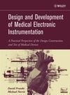
tremendously over the past few years. Unfortunately, college courses and textbooks most
often provide only a cursory view of the technology behind medical instrumentation. This
book supplements the existing literature by providing background and examples of how
medical instrumentation is actually designed and tested. Rather than delve into deep theoretical
considerations, the book will walk you through the various practical aspects of implementing
medical devices.
The projects presented in the book are truly unique. College-level books in the field of
biomedical instrumentation present block-diagram views of equipment, and high-level
hobby books restrict their scope to science-fair projects. In contrast, this book will help
you discover the challenge and secrets of building practical electronic medical devices,
giving you basic, tested blocks for the design and development of new instrumentation.
The projects range from simple biopotential amplifiers all the way to a computer-controlled
defibrillator. The circuits actually work, and the schematics are completely readable.
The project descriptions are targeted to an audience that has an understanding of
circuit design as well as experience in electronic prototype construction. You will understand
all of the math if you are an electrical engineer who still remembers Laplace transforms,
electromagnetic fields, and programming. However, the tested modular circuits and
software are easy to combine into practical instrumentation even if you look at them as
“black boxes” without digging into their theoretical basis. We will also assume that you
have basic knowledge of physiology, especially how electrically excitable cells work, as
well as how the aggregate activities of many excitable cells result in the various biopotential
signals that can be detected from the body. For a primer (or a refresher), we recommend
reading Chapters 6 and 7 of Intermediate Physics for Medicine and Biology, 3rd ed.,
by Russell K. Hobbie (1997).
Whether you are a student, hobbyist, or practicing engineer, this book will show you
how easy it is to get involved in the booming biomedical industry by building sophisticated
instruments at a small fraction of the comparable commercial cost.
The book addresses the practical aspects of amplifying, processing, simulating, and
evoking these biopotentials. In addition, in two chapters we address the issue of safety in
the development of electronic medical devices, bypassing the difficult math and providing
lots of insider advice.
In Chapter 1 we present the development of amplifiers designed specifically for the
detection of biopotential signals. A refresher on op-amp-based amplifiers is presented in the
context of the amplification of biopotentials. Projects for this chapter include chloriding silver
electrodes, high-impedance electrode buffer array, pasteless bioelectrode, single-ended
electrocardiographic (ECG) amplifier array, body potential driver, differential biopotential
amplifier, instrumentation-amplifier biopotential amplifier, and switched-capacitor surface
array electromyographic amplifier.
In Chapter 2 we look at the frequency content of various biopotential signals and discuss
the need for filtering and the basics of selecting and designing RC filters, active filters, notch
filters, and specialized filters for biopotential signals. Projects include a dc-coupled biopotential
amplifier with automatic offset cancellation, biopotential amplifier with dc rejection,
ac-coupled biopotential amplifier front end, bootstrapped ac-coupled biopotential amplifier,
biopotential amplifier with selectable RC bandpass filters, state-variable filter with tunable
cutoff frequency, twin-T notch filter, gyrator notch filter, universal harmonic eliminator
notch comb filter, basic switched-capacitor filters, slew-rate limiter, ECG amplifier with
pacemaker spike detection, “scratch and rumble” filter for ECG, and an intracardiac electrogram
evoked-potential amplifier.
In Chapter 3 we introduce safety considerations in the design of medical device prototypes.
We include a survey of applicable standards and a discussion on mitigating the dangers
of electrical shock. We also look at the way in which equipment should be tested for
compliance with safety standards. Projects include the design of an isolated biopotential
amplifier, transformer-coupled analog isolator module, carrier-based optically coupled analog
isolator, linear optically coupled analog isolator with compensation, isolated eight-channel
12-bit analog-to-digital converter, isolated analog-signal multiplexer, ground bond
integrity tester, microammeter for safety testing, and basic high-potential tester.
In Chapter 4 we discuss international regulations regarding electromagnetic compatibility
and medical devices. This includes mechanisms of emission of and immunity against
radiated and conducted electromagnetic disturbances as well as design practices for electromagnetic
compatibility. Projects include a radio-frequency spectrum analyzer, near-field
H-field and E-field probes, comb generator, conducted emissions probe, line impedance stabilization
network, electrostatic discharge simulators, conducted-disturbance generator,
magnetic field generator, and wideband transmitter for susceptibility testing.
In Chapter 5 we present the new breed of “smart” sensors that can be used to detect
physiological signals with minimal design effort. We discuss analog-to-digital conversion
of physiological signals as well as methods for high-resolution spectral analysis. Projects
include a universal sensor interface, sensor signal conditioners, using the PC sound card as
a data acquisition card, voltage-controlled oscillator for dc-correct signal acquisition
through a sound card, as well as fast Fourier transform and high-resolution spectral estimation
software.
In Chapter 6 we discuss the need for artificial signal sources in medical equipment
design and testing. The chapter covers the basics of digital signal synthesis, arbitrary signal
generation, and volume conductor experiments. Projects include a general-purpose signal
generator, direct-digital-synthesis sine generator, two-channel digital arbitrary waveform
generator, multichannel analog arbitrary signal source, cardiac simulator for pacemaker
testing, and how to perform volume-conductor experiments with a voltage-to-current converter
and physical models of the body.
In Chapter 7 we look at the principles and clinical applications of electrical stimulation
of excitable tissues. Projects include the design of stimulation circuits for implantable
pulse generators, fabrication of implantable stimulation electrodes, external neuromuscular
stimulator, TENS device for pain relief, and transcutaneous/transcranial pulsed-magnetic
neural stimulator.
In Chapter 8 we discuss the principles of cardiac pacing and defibrillation, providing a
basic review of the electrophysiology of the heart, especially its conduction deficiencies
and arrhythmias. Projects include a demonstration implantable pacemaker, external cardiac
pacemaker, impedance plethysmograph, intracardiac impedance sensor, external
defibrillator, intracardiac defibrillation shock box, and cardiac fibrillator.
The Epilogue is an engineer’s perspective on bringing a medical device to market. The
regulatory path, Food and Drug Administration (FDA) classification of medical devices,
and process of submitting applications to the FDA are discussed and we look at the value
of patents and how to recruit venture capital.
Finally, in Appendix A we provide addresses, Web sites, telephone numbers, and fax
numbers for suppliers of components used in the projects described in the book. The contents
of the book’s ftp site, which contains software and information used for many of
these projects, is given in Appendix B.
DAVID PRUTCHI
MICHAEL NORRIS
 TABLE OF CONTENTS