Preface
In this book, methods of adaptive signal processing are borrowed from the field of digital signal processing to solve problems in dynamic systems control. Adaptive filters, whose design and behavioral characteristics are well known in the signal processing world, can be used to control plant dynamics and to minimize the effects of plant disturbance. Plant dynamic control and plant disturbance control are treated herein as two separate problems. Optimal least squares methods are developed for these problems, methods that do not interfere with each other. Thus, dynamic control and disturbance canceling can be optimized without one process compromising the other. Better control performance is the result. This is not always the case with existing control techniques. Inverse control of plant dynamics involves feed-forward compensation, driving the plant with a filter whose transfer function is the inverse of that of the plant. Inverse compensation is well known in signal processing and communications. Every MODEM in the world uses adaptive filters for channel equalization. Similar techniques are described here for plant dynamic control. Inverse control is feed-forward control. The same precision of feedback that is obtained with existing control techniques is also obtained with adaptive feed-forward control since feedback is incorporated in the adaptive algorithm for obtaining the parameters of the feed-forward compensator. Inverse control can be used effectively with minimum phase and non-minimum phase plants. It cannot work with unstable plants, however. They must first be stabilized with conventional feedback, of any design that simply achieves stability. Then the plant and stabilizing feedback can be treated as an equivalent stable plant that can be controlled in the usual way with adaptive inverse control. Model reference control can be readily incorporated into adaptive inverse control. Adaptive noise canceling techniques are described that allow optimal reduction of plant disturbance, in the least squares sense. Adaptive noise canceling does not affect inverse control of plant dynamics. Inverse control of plant dynamics does not affect adaptive disturbance canceling. If initial feedback is needed to provide plant stabilization, the design of the stabilizer has no effect on the optimality of the adaptive disturbance canceler. The designs of the adaptive inverse controller and of the adaptive disturbance canceler are quite simple once the control engineer gains a mastery of adaptive signal processing. This book provides an introductory presentation of this subject with enough detail to do system design. The mathematics is simple and indeed the whole concept is simple and easy to implement, especially when compared with the complexity of current control methods. Adaptive inverse control is not only simple, but it affords new control capabilities that can often be superior to those of conventional systems. Many practical examples and applications are shown in the text. Another feature of adaptive inverse control is that the same methods can be applied to adaptive control of nonlinear plants. This is surprising because nonlinear plants do not have transfer functions. But approximate inverses are possible. Experimental results with nonlinear plants have shown great promise. Optimality cannot be proven yet, but excellent results have been obtained. This is a very promising subject for research. The whole area of nonlinear adaptive filtering is a fascinating research field that already shows great results and great promise. This book was originally published under the title Adaptive Inverse Control. We are grateful to IEEE Press and John Wiley, Inc. for bringing it back into print. We are also grateful to colleagues Gene Franklin, Karl Johan Astrom, Jose Cruz, Brian Anderson, Paul Werbos, and Shmuel Merhav for their early comments, suggestions, and feedback. We are grateful to former Stanford students Steve Piche, Michel Bilello, Gregory Plett, and Ming-Chang Liu who confirmed the results with experiments and who assisted with preparation of the drawings and final manuscript. Bernard Widrow Eugene Walach |
 TABLE OF CONTENTS
 Chapter 10.2.2 - 10.2.2 Adaptive MIMO Modeling Using Scheme C
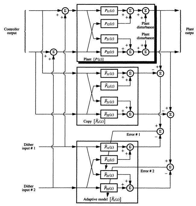
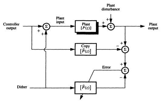
10.2.2 Adaptive MIMO Modeling Using Scheme C As scheme C was often the preferable choice for SISO systems, it is of course important to consider its application to MIMO systems. Figure 10.13 shows a detailed plan for a two-channel MIMO application of scheme C. Figure 10.14 gives an overview vector diagram for general use of scheme C for plant modeling in a multichannel MIMO system. Figure 10.15 shows half of the two-channel modeling modeling process of Fig. 10.13. Since it and the other half act independently, adaptive behavior can be determined by its study. We attempted to relate the behavior of the system of Fig. 10.15 to that of the one-dimensional SISO system of scheme C (shown in Fig. 4.3(c)), but this did not work out. Such an approach worked out well for scheme B above, but failed for scheme C because of the presence of To analyze the system of Fig. 10.15 in order to gain an understanding of the system of Fig. 10.13, it is necessary to go back to fundamentals. We will use the analytical techniques developed in Section B.4.
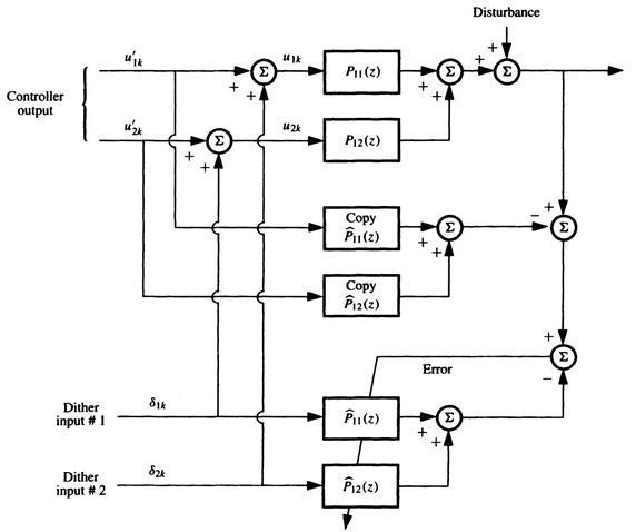
Figure 10.12 Detailed diagram of two-channel MIMO modeling with alternative dither.
Figure 10.13 Scheme C for two-input two-output plant modeling.
Figure 10.14 A vector signal diagram of scheme C for MIMO plant modeling.
The average mean square error can be written as
If we assume that the dither power is the same on both channels, and if we assume that the controller output power is the same on both channels,
Note that
The expectation These expressions can be generalized for the multi-input case. Assume again that the dither powers are equal from channel to channel, and that the controller output powers are equal from channel to channel. The number of channels is designated by K. Accordingly,
Figure 10.15 A part of the two-channel MIMO modeling process in accord with scheme C.
The misadjustment can be obtained by combining (10.18) with (10.21):
For stability, µ must be positive and small enough so that M remains finite. The stable range of µfor MIMO scheme C is
If the controller output power differed from channel to channel, and/or the dither power differed from channel to channel, new expressions for misadjustment and stable range could be derived using similar analytical techniques. |
 11 COPY and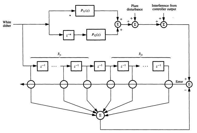


 is the dither power on one channel, and
 is the controller output power on one channel. The average mean square error can be written as
 is the power level on a single-input channel to the plant.