Structural and Stress Analysis, Second Edition

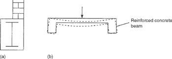
Torsion in beams arises generally from the action of shear loads whose points of application do not coincide with the shear centre of the beam section. Examples of practical situations where this occurs are shown in Fig. 11.1 where, in Fig. 11.1(a), a concrete encased I-section steel beam supports an offset masonry wall and in Fig. 11.1(b) a floor slab, cast integrally with its supporting reinforced concrete beams, causes torsion of the beams as it deflects under load. Codes of Practice either imply or demand that torsional stresses and deflections be checked and provided for in design.
The solution of torsion problems is complex particularly in the case of beams of solid section and arbitrary shape for which exact solutions do not exist. Use is then made of empirical formulae which are conveniently expressed in terms of correction factors based on the geometry of a particular shape of cross section. The simplest case involving the torsion of solid section beams (as opposed to hollow cellular sections) is that of a circular section shaft or bar. Therefore, this case forms an instructive introduction to the more complex cases of the torsion of solid section, thin-walled open section and closed section beams.
Initially, as in the cases of bending and shear, we shall examine the physical aspects of torsion.
Suppose that the circular section bar shown in Fig. 11.2(a) is cut at some point along...