Structural and Stress Analysis, Second Edition

16.10: MOMENT DISTRIBUTION

16.10 MOMENT DISTRIBUTION

Examples 16.15 and 16.16 show that the greater the complexity of a structure, the greater the number of unknowns and therefore the greater the number of simultaneous equations requiring solution; hand methods of analysis then become extremely tedious if not impracticable so that alternatives are desirable. One obvious alternative is to employ computer-based techniques but another, quite powerful hand method is an iterative procedure known as the moment distribution method. The method was derived by Professor Hardy Cross and presented in a paper to the ASCE in 1932.

PRINCIPLE

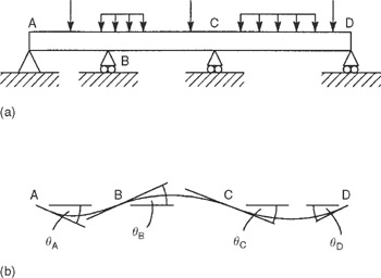
Consider the three-span continuous beam shown in Fig. 16.37(a). The beam carries loads that, as we have previously seen, will cause rotations, ? A, ? B, ? C and ? D at the supports as shown in Fig. 16.37(b). In Fig. 16.37(b), ? A and ? C are positive (corresponding to positive moments) and ? B and ? D are negative.


Figure 16.37: Principle of the moment distribution method

Suppose that the beam is clamped at the supports before the loads are applied, thereby preventing these rotations. Each span then becomes a fixed beam with moments at each end, i.e. FEMs. Using the same notation as in the slope deflection method these moments are M F AB, M F BA, M F BC, M F CB, M F CD and M F DC. If we now release the beam at the support B, say,...

UNLIMITED FREE
ACCESS
TO THE WORLD'S BEST IDEAS

SUBMIT
Already a GlobalSpec user? Log in.

This is embarrasing...

An error occurred while processing the form. Please try again in a few minutes.

Customize Your GlobalSpec Experience

Category: Beams, Joists, and Wall Studs
Finish!
Privacy Policy

This is embarrasing...

An error occurred while processing the form. Please try again in a few minutes.