The Mould Design Guide

13.5: Application of Shrinkage Allowance on Thread Forms

13.5 Application of Shrinkage Allowance on Thread Forms

Clearly, in general, the higher the material shrinkage, the larger cavity and core sizes have to be to compensate. However, account has to be taken of impression structure and form before applying a global shrinkage allowance to all dimensions.

Often there are cavity or core forms that will restrict the full amount of shrinkage taking place, and moulding a screw thread gives a perfect example of such a restriction the actual thread form itself. The thread form is a continuous helical undercut and as such it will prevent free, unrestricted shrinkage that would otherwise take place.

This suggests that a lower shrinkage factor should be applied to the pitch than to the thread diameters, where such restrictions do not exist. This becomes increasingly important as the thread accuracy requirements increase.

For such applications it is suggested that a reduced shrinkage allowance of 0.75 of the normal shrinkage allowance be applied.

13.5.1 Shrinkage Formulae

The following two formulae will assist in establishing the shrinkage sizes for basic thread forms for most purposes. In these formulae, the symbols have the following meanings:

CS = Cavity and core sizes

DS = Drawing sizes

SA = Shrinkage allowance in %

Thread diameters


Thread Pitch


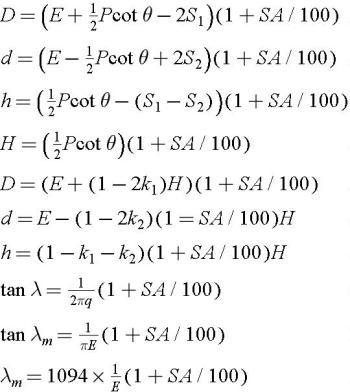
For more critical requirements the full range of shrinkage compensation formulae are listed below:


UNLIMITED FREE
ACCESS
TO THE WORLD'S BEST IDEAS

SUBMIT
Already a GlobalSpec user? Log in.

This is embarrasing...

An error occurred while processing the form. Please try again in a few minutes.

Customize Your GlobalSpec Experience

Category: Thread Gages
Finish!
Privacy Policy

This is embarrasing...

An error occurred while processing the form. Please try again in a few minutes.