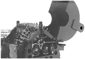
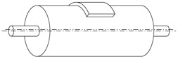
Practical Balancing of Rotating Machinery

Rotor Balancing

The illustration below shows a typical aircraft engine rotor mounted in a horizontal balancing machine. The shaft is located on rollers. There is an end thrust roller to restrain the axial motion note that is mounted to the upper part of the machine. There is a safety shroud with interlock switch. The shroud keeps the operator from touching the spinning rotor and retains objects such as balancing weights (the object is called a weight and we classify it by its mass). The shroud also reduces the amount of drive power needed and avoids generating airflow that would mess up the operator's hairstyle. Not visible in the picture is the drive belt around the shaft to spin the rotor.

This setup enables us to spin the rotor so that the unbalance will generate centrifugal force reactions at the bearings and result in signals produced by the pickups (transducers). In other words we get signals we can filter to show unbalance amount and angle. Once we know that we can correct the unbalance.

Rotor Axes

Here we have a rotor.

It would mount in service, and in a balancing machine, by the bearing journals. In this case we do not have to worry about tooling, etc. The rotor has a bearing axis defined by the centerlines of the two bearing journals. It has a mass axis defined by the rotor mass distribution. Here we see a symmetrical rotor but with a large additional mass on the OD at the...

UNLIMITED FREE
ACCESS
TO THE WORLD'S BEST IDEAS

SUBMIT
Already a GlobalSpec user? Log in.

This is embarrasing...

An error occurred while processing the form. Please try again in a few minutes.

Customize Your GlobalSpec Experience

Category: Balancing Machines and Systems
Finish!
Privacy Policy

This is embarrasing...

An error occurred while processing the form. Please try again in a few minutes.