Everyone has probably heard that design (synthesis) is the reverse of analysis, but most undergraduate courses spend more time on analysis than on design. Consequently, design is not a very familiar, or comfortable, procedure for most students. The saying that design is the reverse of analysis sounds straightforward, but there is a hidden assumption in the saying that implies that the student really understands analysis so that properties of analysis results can be used to synthesize solutions to a problem. This chapter reviews several properties of circuit analysis that are not so well known but are useful to the network design process. Concepts covered here include loop and node parameter matrices, the prototype network concept, impedance and frequency scaling, and some simple network transformation procedures.
2.1 Network Parameter Matrices
Whenever loop current variables are used to analyze a circuit, it is possible to arrange the equations into a matrix form that looks like the analysis of a series RLC circuit. This form is shown in (2.1):
| (2.1) | 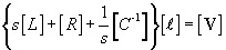
|
where s is complex frequency, [ ?] is a column vector of loop current variables, [ V] is a column vector of loop source voltages, and [ L], [ R], and [ C -1] are loop parameter inductance, resistance, and reciprocal capacitance matrices, respectively. [1] The circuit shown in Figure 2.1 interprets the set of equations in series form for a one-dimensional set of variables.
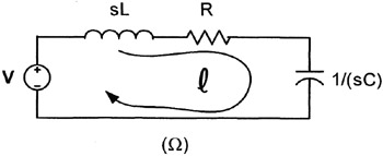 Figure 2.1: The series RLC loop-variable form.
 Alternately, when node voltage...
Copyright ARTECH HOUSE, INC. 2005 under license agreement with Books24x7


 TABLE OF CONTENTS