The concept of surface wave antennas (SWA) was initiated in the 1950s [1 2] and numerous theoretical and experimental investigations have been reported in the literature [3 10]. To support the propagation of surface waves, a commonly used structure in SWA designs is a corrugated metal surface. However, the corrugated structure is thick, heavy, and costly, which may limit the applications of surface wave antennas in wireless communication systems.
In this chapter, novel surface wave antennas are presented. Compared to traditional SWA designs, surface waves are now guided along a thin grounded slab loaded with periodic patches, resulting in a low profile conformal geometry. In contrast to the previous wire-EBG antennas or patch antennas that radiate to the broadside direction, the proposed SWA achieve a monopole-like radiation pattern with a null in the broadside direction. The low profile SWA is more attractive than a traditional monopole antenna that is a quarter-wavelength high.
7.1 A Grounded Slab Loaded with Periodic Patches
7.1.1 Comparison of two artificial ground planes
We start with analyzing a complex artificial ground plane, which will be subsequently used in surface wave antenna designs. Figure 7.1 shows two artificial surfaces: a mushroom-like EBG surface and a grounded dielectric slab loaded with periodic patches. In the latter structure vertical vias are removed, which results in different surface wave properties in the two ground planes.
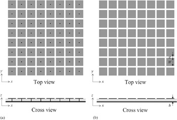 Fig. 7.1: Geometry of two artificial ground planes: (a) a mushroom-like electromagnetic band gap (EBG) structure and (b) a grounded dielectric slab loaded with periodic patches.
Copyright Cambridge University Press 2009 under license agreement with Books24x7


 TABLE OF CONTENTS