Elements of 3D Seismology, 2nd Edition

Developed from university courses, this text provides a thorough introduction to the acquisition, processing, and interpretation of 3-D seismic data, theory, techniques, and applications.
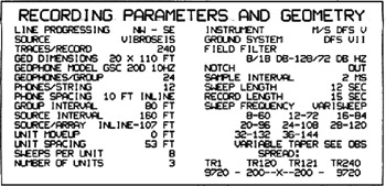
Acquisition geometry for 2D seismic data contains many elements common to 3D acquisition. We will review 2D acquisition by going, in detail, through items in the geometry section of the line header for a specific West Texas seismic line (Fig. 7.1) shot for Unocal in 1990. Where it will clarify matters, throughout the description the original item name will be placed in capitals and parentheses (e.g., traces/record) for reference. In this chapter, we deviate from the preferred metric system because the line header lengths are in English units. However, the concepts given here are equally valid for a 2D seismic line shot with metric intervals. Rather than go pedantically through the items from first to last, we subdivide them into topics.
With respect to the general topic of seismic data acquisition, there are a number of ways to subdivide the subject [100]. A natural one is land, marine, and transition zone. A second is to consider subsystems source, receiver, recording, positioning but this classification depends heavily on the application. A third approach is to distinguish hardware from field procedures. In general, we follow the third approach here.