Elements of 3D Seismology, 2nd Edition

Developed from university courses, this text provides a thorough introduction to the acquisition, processing, and interpretation of 3-D seismic data, theory, techniques, and applications.
In this chapter, we highlight those reservoir properties that affect amplitude as observed on seismic data. As a seismic ray progresses from source to receiver, many factors influence the amplitude. There is a source radiation pattern determined by source type, array, and coupling (see chapter 1.10). As the ray travels, there is continuous amplitude loss due to geometric spreading (see chapter 1.16.2). There is further continuous loss due to absorption (see chapter 6.8). Each time the ray passes through an impedance contrast interface, the amplitude is scaled by a transmission coefficient leading to cumulative transmission losses (see chapter 20.1.7).
In the reflection process, the amplitude is scaled by an angular reflection coefficient (see chapters 3.2.2, 5.9, 5.10). As the ray passes back up toward the acquisition surface, the amplitude is further reduced by more geometric spreading, absorption, and transmission loss. Finally, the amplitude measured by the receiver is a function of the returned amplitude, receiver coupling, and array directivity.
This seismic ray amplitude history can be summarized in the relationship
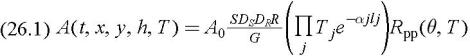
where the symbols are defined in Table 26.1.
| Symbol | Definition |
|---|---|
| A | observed amplitude |
| A 0 | amplitude emitted by source |
| ? j | absorption factor of layer j |
| D s, D g | source and receiver directivity functions |
| G | geometric spreading function |
| ? | product symbol |
| R pp( ?, T) | elastic P-P reflection coefficient |
| t | reflection time |
| T | acquisition date (vintage) |
| T j | transmission coefficient of interface j |
| ? | reflection incidence... |