Engineering Computations: International Journal for Computer-Aided Engineering and Software: The Discrete Element Method: Numerical Modelling of Discontinua, Volume 21, Number 2/3/4, 2004

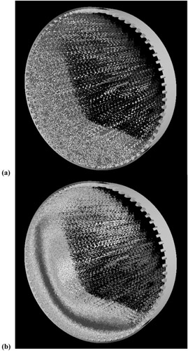
Plant scale SAG mills are generally modelled using only a narrow slice from the middle of the mill. Figure 11 shows the charge distribution predicted in a 0.5 m section of a 36 in. SAG mill. There are 72 rows of symmetric close packed steep face lifters (7 ). The mill speed is 10 rpm (78 per cent critical), the charge fill level is 30 per cent and the ball load is 10 per cent. The ball and rock size distributions are fairly generic and are truncated at a bottom size of 25 mm. This gives a DEM model with 184,000 particles. The charge surface has a very clear bi-linear shape, rising slowly from the toe to the middle of the charge and then steeply up to the shoulder. A substantial cataracting stream departs from the lifters above the shoulder and falls in well defined streams to impact on the liner above the toe at around the 3 o'clock position. Radial segregation is very clear with a concentration of fine particles against the mill shell and in the upper part of the cataracting stream.
The model prediction of power drawn is 778 kW/0.5 m mill slice, so for a typical 6 m long SAG mill the total power drawn is 9,320 kW. This is very close to the...