Fundamentals of Nonlinear Behavioral Modeling for RF and Microwave Circuits

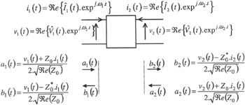
The modeling problem stated in Section 3.1 is summarized in Figure 3.6. The signal at each port consists only of a single envelope around the port carrier, noted ? 1 or ? 2, which, as mentioned earlier, is a by-product of the base carriers ? RF and ? LO.
Now to proceed further, it is of importance to define precisely our notion of excitation and response variables, which we will henceforth note
and ?( t), respectively. According to Figure 3.6, we may chose either of the power waves or voltage-current formalism as defined in Table 3.1. In the rest of this chapter, we will consider the power wave formalism.
| Excitation | Response | |
|---|---|---|
| Voltage-current formalism | | ?( t) = [ 1( t), 2( t)] T |
| Power wave formalism | | |
With
and ?( t) as the system excitation and response signals, the very general form of the constitutive equation that accounts for the bloc nonlinear dynamics can be noted as:
| (3.5) | |
Equation (3.5) constitutes the minimal or nominal relationship that has to be identified by the modeling process. This involves only the electrical variables at the bloc ports. In practice however it is often necessary to characterize the dependence of this relationship on some critical design parameter (temperature, bias voltage, and so forth), in...