Gas Lift Manual
Including ample illustrations to help the reader understand the text, this handy reference is essential to the practicing engineer needing to successfully perform this type of artificial lift project.
Description
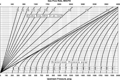
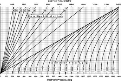
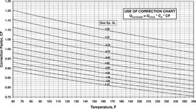
Figures C-1 and C-2 present gas capacity charts for square-edge orifices of different sizes and allow the calculation of gas flow rates for different combinations of upstream and downstream pressures. Calculations are based on the following assumptions: Gas Sp. Gr. = 0.65; C d = 0.865 1 T 1 = 60 F. For other gas specific gravities, discharge coefficients and flowing temperatures, the gas rates found from these figures must be corrected according to Figure C-3.
Example problem
Find the gas passage capacity of an 30/64 ? choke, if upstream and downstream pressures are 800 psig and 600 psig, respectively. Gas specific gravity is 0.7, flowing temperature is 100 F, and a discharge coefficient of 0.9 is to be used.
Solution
Based on the choke size, Figure C-2 is to be used. Start at an upstream pressure of 800 psig and go vertically until crossing the curve valid for a downstream pressure of 600 psia. From the intersection, draw a horizontal to the left to the proper choke size (30/64 ?). Drop a vertical from here to the upper scale to find the gas flow rate of 3,432 Mscf/d. Since actual flow conditions differ from chart base values, the correction as given in Figure C-3 must be applied. At a temperature of 100 F and a gas specific gravity of 0.7 the correction factor is read to be equal CF=1.072. Corrected gas volume is according to the formula in...