Modern Microwave Circuits

Including over 1,200 equations and more than 300 illustrations, this invaluable book explains how microstrip circuits are built and provides in-depth coverage of computer-aided simulation and underlying theories.
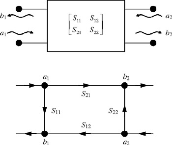
Analysis of complex circuits by using scattering matrixes can be difficult due to involved matrix algebra. Besides, analysis using matrix algebra does not provide much insight to actual physical interactions through the circuits. Signal flowgraphs eliminate this and provide an alternative way of analyzing circuits using scattering waves. In signal flowgraphs, each node is represented by a particular wave name and lines connecting these nodes represent interactions between the relative waves as depicted in Figure 1.23. Note that the two-port circuit shown in the figure now has four wires connecting to the external world where each of them carries one of the four traveling waves. And the nodes are labeled in order to facilitate easy connection for cascading circuits.
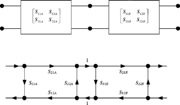
To cascade two circuits, one just needs to connect the appropriate wires of the flowgraphs as depicted in Figure 1.24. This can be easily generalized to any number of ports and circuit topologies. To find the transmission between any nodes, one traverses the existing connections between those nodes (by paying attention to the direction of arrows) and multiplies the signal by the gain factor of each connection. Of course, feedbacks should be taken into account during this process.
The resulting equation obtained using the signal flowgraphs may not be simpler than the one achieved through matrix manipulation of scattering equations, but it is usually faster...