Sucker-Rod Pumping Manual
Full of illustrations, tables, and formulas, this book will provide the reader with everything they need to ensure successful sucker-rod pumping operations.
The function of speed reducers, more commonly called gear reducers, is to reduce the high rotational speed of the prime mover to the pumping speed required. The usual speed reduction ratio is about 30:1, the maximum output speed is about 20 strokes per minute. Speed reducer sizes are standardized by the API in Spec. 11E, the rating relates to the maximum torque allowed on the reducer. [55] The standard peak torque range is from 6,400 in-lbs (720 Nm) to 3,648,000 in-lbs (412,170 Nm), and the corresponding sizes are designated as 6.4 and 3,648. These ratings are valid for a pumping speed of 20 strokes per minute, up to the reducer size 320, above which the maximum allowed speeds are reduced. Two kinds of speed reducers are used: geared and chain reducers.
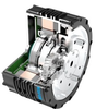
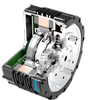
Gear reducers utilize double or triple reduction gearing; Figure 2-60 shows a schematic of a double-reduction unit. It contains three shafts: the high-speed input shaft, an intermediate, and a slow-speed shaft. The highspeed shaft is driven by the prime mover through a V-belt sheave, and the slow-speed shaft drives the crank arms of the pumping unit. Since torque is increased at every shaft as speed is reduced, shaft diameters are also increased with the decrease of speed. They are designed to withstand the high torsional and bending loads and ensure that the gear faces are in full contact even at the rated torque of the reducer. The shafts run in bearings mounted in the reducer housing.