USB Design by Example: A Practical Guide to Building I/O Devices, Second Edition

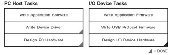
In Chapter 4, we learned that an I/O device consists of a USB transceiver, a Serial Interface Engine, a Protocol Controller (typically a microcontroller), and interfaces to the real world. The microcontroller will also run application firmware that implements the functionality of the I/O device. The I/O device will communicate with the PC Host using standard USB protocols, and they will exchange data blocks. A program on the PC Host will be responsible for coordinating the actions of the I/O device. Wow! A typical USB application involves a lot of software and running on two processors! Fortunately the development process is well defined and there are many tools available. Figure 5-1 shows the tasks that must be completed to implement a working USB I/O device design some of the tasks have already been taken care of, so we need only focus on the unique aspects of our I/O device design.
It should be stressed at this time that the PC host and I/O device communicate using standard protocols this means that the implementation of the I/O device is unknown to the PC host. The software on the PC host does not change, no matter how we implement the I/O device. This separation of tasks gives us some design freedom we could implement an easier, over-featured I/O device as a prototype then cost-reduce the solution at a later time. (I shall use this strategy focusing on functionality in Chapter...