USB Design by Example: A Practical Guide to Building I/O Devices, Second Edition

In this chapter, we ll build a simple I/O device, using what we learned about PC host software in Chapter 6 and what we learned about the responsibilities of an I/O device in Chapters 2 and 3. I chose the simplest design that I could think of, so that it would be easier to focus on the method: this design has a single 8-bit input port to which we will connect eight buttons and it has a single 8-bit output port to which we will connect eight LEDs.
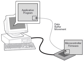
Figure 7-1 represents the overall design task. A PC host application program writes blocks of data to an I/O device and reads buffers of data from an I/O device. The format of these data buffers will be known by the application program and by the microcontroller firmware.
We ll eventually have multiple examples; for that reason, each I/O device, its hardware, and its matching firmware must be uniquely identified by its Product Code and Name. The PC host application program will first open a named I/O device to ensure that the hardware matches the software. The program will also close the connection as it exits.
When you develop an I/O device, you choose a USB interface and a microcontroller (or a microcontroller with a USB interface), and the required real world I/O interfaces (for guidance, see Appendix A). Then you write the subroutines that respond to the commands sent by the...