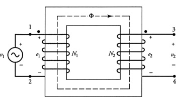
4.3: An Ideal Transformer
4.3 An Ideal Transformer
A two-winding transformer with each winding acting as a part of a separate electric circuit is shown in Figure 4.3. Let N 1 and N 2 be the number of turns in the primary and secondary windings. The primary winding is connected to a time-varying voltage source v 1 while the secondary winding is left open. For the sake of understanding, let us first consider an idealized transformer in which there are no losses and no leakage flux. In other words, we are postulating the following:
-
The core of the transformer is highly permeable in a sense that it requires vanishingly small magnetomotive force (mmf) to set up the flux ? as shown in the figure.
-
The core does not exhibit any eddy-current or hysteresis loss.
-
All the flux is confined to circulate within the core.
-
The resistance of each winding is negligible.
Figure 4.3: An idealized transformer under no load.
According to Faraday's law of induction, the magnetic flux ? in the core induces an emf e 1 in the primary winding that opposes the applied voltage v 1. For the polarities of the applied voltage and the induced emf, as indicated in the figure for the primary winding, we can write
Similarly, the induced emf in the secondary winding is
with its polarity as indicated in the figure.
In the idealized case assumed, the induced emf's e 1 and e 2 are equal to the...