Logic Comparators Information
Last revised: November 20, 2024
Reviewed by: Scott Orlosky, consulting engineer
Digital comparators are integrated circuits (ICs) that compare the magnitude of two binary quantities and determine the relationship of those quantities. There are two basic types of digital comparators: identity comparators and magnitude comparators.
Identity comparators indicate whether two inputs are equal. Magnitude comparators indicate whether two inputs are equal and, if they are not, which input is larger or smaller. Typically, digital comparators are used to compare an input voltage to a reference voltage.
Logic circuits that incorporate multiple individual comparators are able to characterize large groups of input signals. Digital comparators may be operated in synchrony with a clock or asynchronously, incorporating sufficient gain to force the output signal into saturation.
Specifications
Digital comparators vary in terms of supply voltage, number of bits, propagation delay, operating current, and operating temperature. Supply voltages range from - 5 V to 5 V and include intermediate voltages such as -4.5 V, -3.3 V, -3 V, 1.2 V, 1.5 V, 1.8 V, 2.5 V, 3 V, 3.3 V, and 3.6 V. The number of bits is the size of the binary numbers that a digital comparator can process. A comparator that has two, four-bit inputs, four example, is called a four-bit comparator.
The propagation delay is the time interval between the application of an input signal and the occurrence of the corresponding output. Like other ICs, digital comparators require a minimum current for active operation and feature a range of operating temperatures. Some digital comparators are radiation-tolerant. Others provide protection against electrostatic discharge (ESD).
How to Select
Selecting digital comparators requires an analysis of logic families. Transistor-transistor logic (TTL) and related technologies such as Fairchild advanced Schottky TTL (FAST) use transistors as digital switches. By contrast, emitter coupled logic (ECL) uses transistors to steer current through gates that compute logical functions.
Another logic family, complementary metal-oxide semiconductor (CMOS), uses a combination of p-type and n-type metal-oxide-semiconductor field effect transistors (MOSFETs) to implement logic gates and other digital circuits.
Logic families for digital comparators include crossbar switch technology (CBT), Gallium arsenide (GaAs), integrated injection logic (I2L) and silicon on sapphire (SOS). Gunning with transceiver logic (GTL) and gunning with transceiver logic plus (GTLP) are also available.
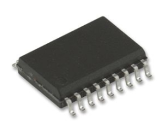
Packaging Options
Digital comparators are available in a variety of IC package types and with different numbers of pins and flip-flops.
Basic IC Package Types
- Ball grid array (BGA)
- Quad flat package (QFP)
- Single in-line package (SIP)
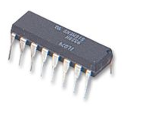
- Dual in-line package (DIP)
BGA Packaging Variants
- Plastic-ball grid array (PBGA)
- Tape-ball grid array (TBGA)
QFP Packaging Variants
- Low-profile quad flat package (LQFP)
- Thin quad flat package (TQFP)
DIPs are available in either ceramic (CDIP) or plastic (PDIP). Other IC package types include small outline package (SOP), thin small outline package (TSOP), and shrink small outline package (SSOP).
Related Standards
JIS B 7536 — Electrical comparators.
NPFC-A-A-58089 — Comparator, bench type, electronically amplified.
DOD DESC-DWG-84151 — Microcircuits, digital, low-power Schottky TTL, magnitude comparator, monolithic silicon.
Logic Comparators FAQs
How do logic comparators differ from analog comparators in terms of functionality?
Logic comparators and other types of comparators, such as analog comparators, differ in terms of functionality in several ways:
Logic Comparators: These are digital devices used to compare two binary numbers and determine their relative magnitudes. They provide outputs indicating whether one number is greater than, less than, or equal to the other. They are typically used in digital circuits and systems where binary data comparison is required.
Analog Comparators: These devices compare two voltage levels and output a digital signal indicating which input is higher. They are often used in applications like A/D converters, level detection, and on-off controls, acting as a bridge between analog and digital domains.
Logic Comparators: The output is typically a set of digital signals representing the comparison results (e.g., A > B, A < B, A = B).
Analog Comparators: The output is a single digital signal that switches states based on the comparison of input voltages. This output is often used to trigger further actions in a circuit.
Logic Comparators: Implemented using digital logic gates and circuits, they are part of digital logic families such as TTL, CMOS, and others.
Analog Comparators: These are designed similarly to operational amplifiers but without feedback, optimized for rapid switching between high and low states. They may include features like hysteresis and latching for stability and control.
Analog Comparators: Used in mixed-signal applications, such as signal conditioning, threshold detection, and waveform shaping.
What are some applications of logic comparators?
Logic comparators are used in digital systems for tasks like sorting, arithmetic operations, and digital signal processing.
What are the advantages of using CMOS over TTL in digital circuits?
Here are the advantages of using CMOS (Complementary Metal-Oxide-Semiconductor) over TTL (Transistor-Transistor Logic) in digital circuits:
Power Consumption
CMOS: Known for its low power consumption, CMOS only draws significant power during the switching of states. This makes it more efficient for battery-powered devices and applications where power efficiency is crucial .
TTL: Generally consumes more power compared to CMOS due to the continuous current flow in the BJT-based design .
Cost and Integration
CMOS: Typically offers lower costs and allows for higher levels of integration, making it suitable for complex and dense circuits .
TTL: Usually more expensive due to higher power consumption and less integration capability .
Noise Immunity and Performance
CMOS: Provides better noise performance and is preferred for applications requiring high noise immunity .
TTL: Offers good noise immunity but is generally outperformed by CMOS in terms of noise margins .
Technology and Structure
CMOS: Uses a combination of p-type and n-type MOSFETs to implement logic gates and other digital circuits, which is the technology of choice for many present-day digital integrated circuits .
TTL: Utilizes bipolar junction transistors (BJTs) as digital switches, which is an older technology .
These advantages highlight why CMOS has become the dominant technology in modern digital circuits, especially for applications requiring low power and high integration.
What are the specific use cases where TTL might still be preferred over CMOS?
High-Speed Applications
TTL, particularly in its Emitter-Coupled Logic (ECL) variant, is known for its high-speed performance. ECL is still in use and is considered the fastest among the BJT-based logic families
Legacy Systems
TTL might be preferred in legacy systems where existing infrastructure and components are based on TTL technology. This can be due to compatibility reasons or the cost of redesigning systems to accommodate CMOS technology.
Noise Immunity
While CMOS generally offers better noise performance, certain TTL variants may still be used in environments where specific noise characteristics of TTL are advantageous.
Temperature Stability
TTL circuits can be more stable over a wider range of temperatures compared to some CMOS circuits, which might be beneficial in certain industrial or military applications.
Driving Capability
TTL circuits often have better current driving capabilities compared to CMOS, which can be beneficial in applications requiring the driving of multiple loads or long signal lines.
These use cases highlight scenarios where TTL might still be relevant despite the widespread adoption of CMOS technology due to its advantages in power consumption, cost, and integration.
What are the advantages of using ECL in high-speed applications?
Emitter-Coupled Logic (ECL) is advantageous in high-speed applications due to several key characteristics:
High-Speed Performance
ECL is known for its ability to operate at very high speeds. This is because the transistors in ECL circuits are always in the active region, allowing them to change states very rapidly. This characteristic makes ECL suitable for applications requiring ultra-fast switching speeds.
Low Propagation Delay
ECL circuits have low gate propagation delays, which is crucial for high-speed digital integrated circuits. This allows for faster data processing and signal transmission, making ECL ideal for high-frequency applications.
High Data Rates
ECL supports high data transfer rates, which is essential for applications that require rapid data processing and transmission, such as high-speed computing and telecommunications.
Temperature Stability
ECL circuits can maintain performance over a wide range of temperatures, which is beneficial in environments where temperature fluctuations are common.
Driving Capability
ECL circuits often have better current driving capabilities compared to other logic families, which can be beneficial in applications requiring the driving of multiple loads or long signal lines.
Logic Comparators Media Gallery
References
GlobalSpec—Digital Principles and Logic Design
GlobalSpec—Logic Level Translators
GlobalSpec—Semiconductor Foundry Services
Image Credits:
1-Source Electronic Components, Inc.