DC Motor Working Principle
DC motors are among the most commonly used electric motors in a broad range of applications today. Like every electric motor, they convert electric energy into mechanical work (in the form of shaft rotation). However, DC motors differ from other electric motors because they are powered by direct current (DC), such as batteries and DC power supplies.
But how exactly do DC motors convert DC electrical energy into shaft rotation? To find the answer to this question, engineers must first understand some fundamental concepts like the Lorentz law and Fleming’s left-hand rule.
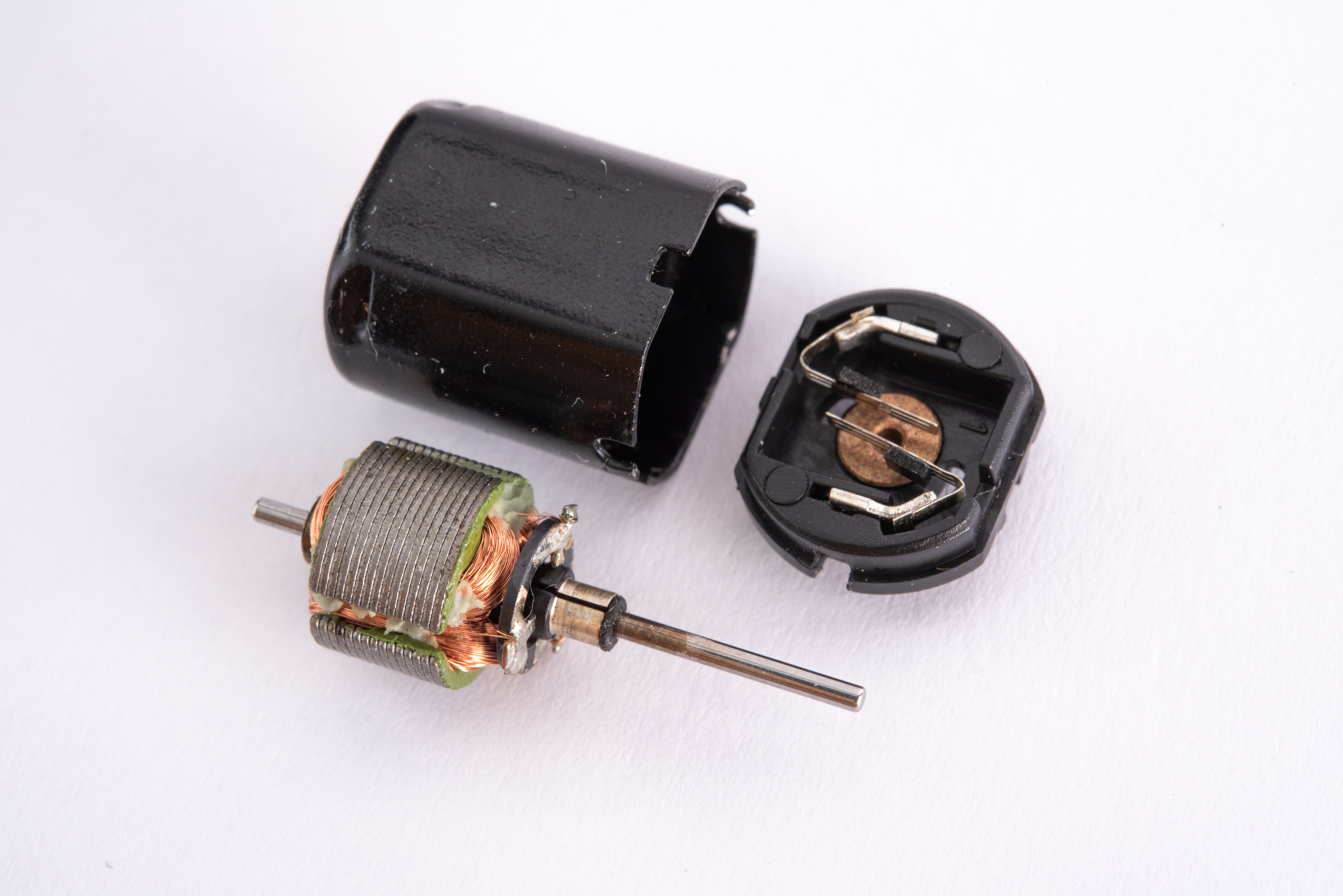
Figure 1: DC motors are powered by direct current sources, such as batteries and DC power supplies
Source: [Meinhard/Adobe Stock]
Understanding the Lorentz force lawImagine a length of ordinary wire is rolled into a big loop and placed between the poles of a powerful horseshoe magnet. If the ends of this wire are connected to a battery, the wire will jump up suddenly. Lorents force law explains why this amazing phenomenon happens.
Lorentz law explains that a current-carrying conductor experiences a force when placed in a magnetic field. When electric current flows through a conductor, it creates a magnetic field around the conductor. This temporary magnetic field interacts with a permanent magnet’s field, attracting (or repelling) the magnetism. As a result, the wire experiences a force that causes it to jump.
The direction of this force (or motion of the conductor) can be obtained using Fleming’s left-hand rule.
Fleming’s left-hand ruleThe Flemming’s rule was developed by John Ambrose Fleming in the 19th century. It is a visual mnemonic that uses the left hand's thumb, index, and middle fingers to determine a conductor’s direction of motion in a magnetic field.
For example, consider a situation where the thumb, index finger, and middle finger are held out so that all three are at right angles, as shown below. Fleming’s rule states that if the middle finger points in the current direction and the index finger points in the magnetic field direction, the thumb points in the direction of the conductor’s thrust.
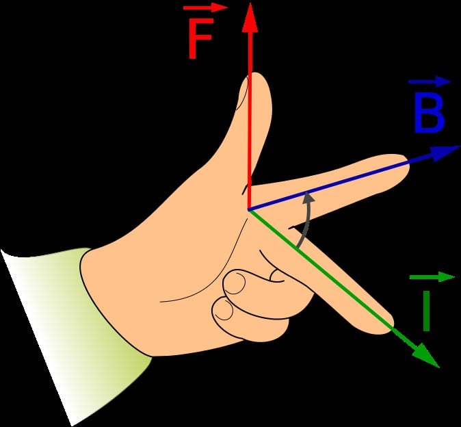
Figure 2: Fleming’s left-hand rule
Source:Jfmelero/CC [SA][3.0]
And the magnitude of this force can be calculated using:
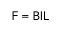
Where:
B = magnetic flux density of the field (measured in Tesla or T)
I = current on the conductor (A)
L = length of the conductor in the field (m)
However, keep in mind that the current direction is from the battery’s positive terminal to the negative terminal, while the magnetic field flows from the magnet’s north pole to the south pole.
Fleming’s rule and the working principle of DC motorsFigure 3 shows the interior of a typical DC motor. It comprises two essential parts: the stator (or the stationary part of the motor) and the rotor (or rotating part of the motor). A DC motor’s stator is usually a ring of permanent magnets. In contrast, the rotor is wrapped several times with a wire and nested into the stator.
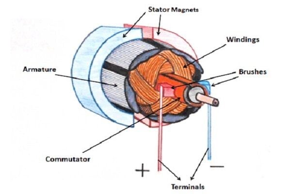
Figure 2: DC motor parts
Source: www.linquip.com
Now when direct current starts flowing through the rotor windings, it causes a magnetic field to be generated around the winding. This magnetic field interacts with the stator’s magnetic field, causing a force to be generated in a direction given by Fleming’s left-hand rule. Because of the way the stator is constructed, this force is manifested as the rotation of the rotor.
Back EMF of DC motors and motor speedThe fundamental laws of energy conservation explain that it is impossible to achieve energy conversion unless there is some form of opposition. In the case of DC motors, this opposition is provided by the back EMF.
Back EMF is the electromotive force that opposes the applied voltage. It is induced in the conductor when the motor’s armature is rotating and cutting across magnetic field lines. The magnitude of back EMF is directly proportional to the speed of the motor, according to the equation below:
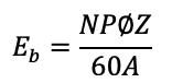
Where:
N = motor speed
P = number of poles
A = number of parallel parts through the armature
Z = total number of conductors in the armature
fi = Flux per pole
Choosing between the different types of DC motorsThere are several types of DC motors, all of which have similar modes of operation but differ in design, efficiency, and capability. For instance, permanent DC motors and series DC motors are among the most commonly used DC motors for many applications today.
[Learn more about the selection criteria for DC motors on GlobalSpec]