RFIC and MMIC Design and Technology

7.4: Analysis of Mixer Circuits

7.4 Analysis of Mixer Circuits

In order to provide some understanding of mixer operation, a simple single loop circuit will now be analysed.

7.4.1 Analysis of a Simple Single-Loop Circuit

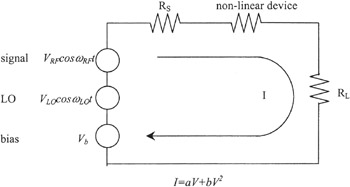
Consider the simple single-loop circuit shown in Figure 7.3. This represents a single-ended mixer design, where all mixed products and intermodulation products are terminated in the source and load resistances, i.e. a wideband mixer design. This circuit will now be examined using both general non-linear analysis and a method of linear circuits with time-varying parameters. The latter method is also referred to as the conversion loss matrix method.


Figure 7.3: A simple single-ended mixer

7.4.2 General Non-Linear Analysis

We begin by combining the source and load resistances with the non-linear device to form a new non-linear equation:

(7.8)

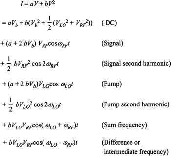
where a, b, c, d are constants and V is the sum of all applied voltages. In the present analysis, we will restrict the power series to the first two terms. After substituting for V and some trivial manipulation, we have:

(7.9)

7.4.2.1 Conversion Loss

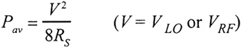
The power available from the signal, P av, is given by:

(7.10)

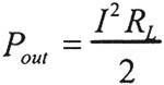
Power into the load at any frequency is given by:

(7.11)

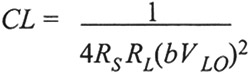
Conversion loss ( CL) is therefore given by:

(7.12)

For ? RF to ? LO ? RF and ? LO ?RF:

(7.13)

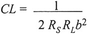
For ? RF to 2 ? RF and ? LO to 2 ? LO:

(7.14)

7.4.2.2

UNLIMITED FREE
ACCESS
TO THE WORLD'S BEST IDEAS

SUBMIT
Already a GlobalSpec user? Log in.

This is embarrasing...

An error occurred while processing the form. Please try again in a few minutes.

Customize Your GlobalSpec Experience

Category: RF Mixers
Finish!
Privacy Policy

This is embarrasing...

An error occurred while processing the form. Please try again in a few minutes.