Theory and Design of Microwave Filters

Chapter 3: Design of Lumped Lowpass Prototype Networks

3.1 Introduction

A lowpass prototype is a passive, reciprocal, normally lossless two-port network which is designed to operate from a 1 ? generator into a 1 ? load. The network response has a lowpass characteristic with its band-edge frequency at ? = 1. The amplitude response of the network is designed to at least meet a minimum specification on passband return loss L R and stopband insertion loss L A. For example,

(3.1)
(3.2)

Since the network is normally lossless there is no need to specify the passband insertion loss since this is related to the return loss by the unitary condition.

There may also be a phase linearity or group delay specification on the passband characteristic of the filter.

The lowpass prototype which may be of lumped or distributed realisation is a 'building block' from which real filters may be constructed. Various transformations may be used to convert it into a bandpass or other filter of arbitrary centre frequency and bandwidth.

3.2 The Maximally Flat Prototype

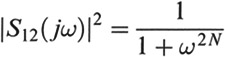
The maximally flat or Butterworth approximation is the simplest meaningful approximation to an ideal lowpass filter. The approximation is defined by [1]

(3.3)

Hence the insertion loss is given by

(3.4)

Now for ? < 1, ? 2 N rapidly becomes very small. For ? > 1, ? 2 N rapidly becomes very large. The 3 dB frequency is at ? = 1 and marks the transition between passband and stopband.

N

UNLIMITED FREE
ACCESS
TO THE WORLD'S BEST IDEAS

SUBMIT
Already a GlobalSpec user? Log in.

This is embarrasing...

An error occurred while processing the form. Please try again in a few minutes.

Customize Your GlobalSpec Experience

Category: IC Electronic Filters
Finish!
Privacy Policy

This is embarrasing...

An error occurred while processing the form. Please try again in a few minutes.