Flexible AC Transmission Systems: Modelling and Control

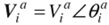
In Fig. 5.1,
,
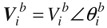
,
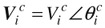
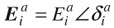
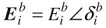
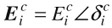
, which are the three-phase voltages at the generator terminal bus, are expressed in phasors in rectangular coordinates. Similarly, the voltages at the generator internal bus may be given by
,
,
. In fact the voltages at the generator internal bus are balanced, that is:
| (5.45) | |
| (5.46) | |
In the three-phase power flow equations of the generator,
and
can be considered as independent state variables of the internal generator bus while
and
, and
and
are dependent state variables and can be represented by
and
. We have:
| (5.47) | |
| (5.48) | |
| (5.49) | |
| (5.50) | |
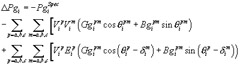
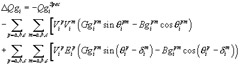
The network buses include all buses of the network except the internal buses of generators. The power mismatch equation of phase p at the network bus i are given by:
| (5.51) | |
| (5.52) | |
where p = a, b, c.
and
are the active and reactive loads of phase p at bus i.
PQ Machines. For a PQ machine, the total three-phase active and reactive powers at the terminal bus of the machine are specified:
| (5.53) | |
| (5.54) | |
where
and
are the specified active and reactive powers of the generator at bus I, which are in the direction of into...