Introduction to Radar Target Recognition
Based on the fundamental scientific principles of high resolution radar, this text covers the key techniques being developed for operational systems, and explains how they can be used in real systems.
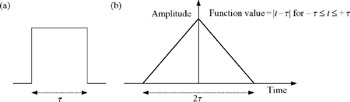
In this appendix, the output of the matched filter for the classical stepped frequency technique is derived. This is required to determine the various properties of the waveform, which affect its applications in target recognition. Initially, in this and the following section, the properties of a basic pulse are presented (Figure A.1). The frequency transform of a pulse on a carrier frequency, f c, of width, ? ?, is:
where F( f, f c) is the frequency transform of time domain signal.
This frequency domain signal is:
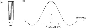
The power spectrum of a pulse of duration ? ? and frequency f c is the square of Equation (A.2):
which is now defined to be a function = { F( f ? f c)} 2.
The output of the matched filter is the auto-correlation [1] of the time domain signal:
where C(t) is the waveform's auto-correlation function, F sig ( ?)* is the complex conjugate of the signal and F sig( t + ?) is the signal shifted in time by t (Figure A.2).