Microcontrollers in Practice
Packed with hundreds of practical examples and exercises to foster mastery of concepts and details, this practical guide provides readers with hands-on knowledge of how to implement three families of microcontrollers.
This chapter contains an overview of the parallel I/O subsystem of the HC11, AVR, and 8051 microcontrollers, from a hardware and software perspective.
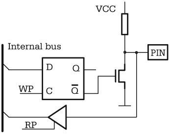
The digital I/O lines are the simplest and most common way microcontrollers interact with the outside world. Figure 2.1 shows how digital input and output lines are connected to the internal bus of the MCU.
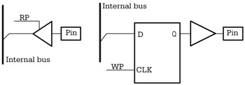
In case of an input line, the status of the MCU pin is transferred on the internal bus to the CPU by activating the internal signal RP (Read Port), generated during the execution of the instruction used to read the port.
An output line is associated with an internal latch, which can be written from the internal bus and the driver connected to the physical pin.
In practice, things are a bit more complicated. For economic and technological reasons, it is more convenient to assign two or more functions to each pin than to double the number of pins of the capsule. This is the reason why all microcontrollers extensively use bi-directional input/output lines. The simplest way to obtain a bi-directional line is to use an open drain driver for the output line. When the output transistor is blocked, an external device can control the line. Figure 2.2 shows the logic diagram of a bi-directional I/O line implemented according to this principle.