Microcontrollers in Practice
Packed with hundreds of practical examples and exercises to foster mastery of concepts and details, this practical guide provides readers with hands-on knowledge of how to implement three families of microcontrollers.
The example presented below is an illustration of a typical structure with 68HC11E9 operating in expanded multiplexed mode (MODA = 1, MODB = 1).
Figure A4.1 shows the microcontroller and the bus demultiplexer, implemented with the latch 74LS573, controlled by the Address Strobe (AS) signal. Note that the unused MCU pins are not represented in this figure.
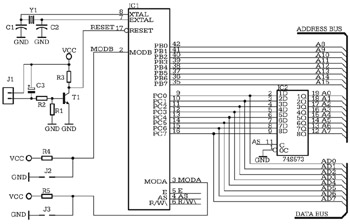
Figure A4.2 shows the external memory circuits and the address decoder. The external ROM is an 8-kilobyte, 2764 EPROM (ICx), selected with CSE000H. ICy is a 6264 8-kilobyte RAM selected with CS2000H. Besides chip select, the 6264 circuit requires an additional control signal for the OE (Output Enable) input. This is OERAM, obtained by inverting the signal R/W\ with the gate IC7A.
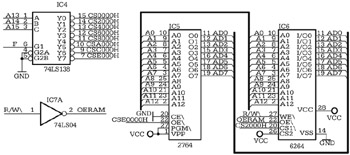
Two additional selection signals CS4000H and CS6000H are used to control the external input and output ports, shown in Fig. A4.3.