Motion Vision: Design of Compact Motion Sensing Solutions for Autonomous Systems Navigation
Part 4: Appendices

Chapter List

Appendix A: System Timing
Appendix B: SDRAM Timing
Appendix C: FPGA Design
Appendix D: Simulation of Range Data

Overview

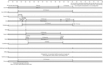
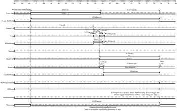
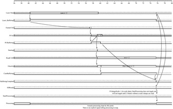
This appendix gives details of our sensor s internal timing and control flow. For illustrative purposes we show the timing and control flow for both a 512 32 pixel image (i.e. the case where there is no subsampling due to scale space) and a 32 32 pixel image (where there is maximal subsampling). After the timing diagrams there is a table detailing the meaning of labels in the diagrams. Note that all diagrams assume 10 Hz operation for the sensor. At higher rates only the inter-frame time changes the timing for individual data elements remains the same.

A.1 Timing for a 512 32 Pixel Image


Figure A.1: Timing for a 512 32 pixel image

A.2 Control Flow for a 512 32 Pixel Image


Figure A.2: Control flow for a 512 32 pixel image

A.3 Timing for a 32 32 Pixel Image


Figure A.3: Timing for a 32 32 pixel image

A.4 Control Flow for a 32 32 Pixel Image


Figure A.4: Control flow for a 32 32 pixel image

A.5 Legend for Timing Diagrams

Time

Description

a

19 ms (max)

Range data input

  • If camera optical axis and laser data 0 axis are aligned then we are taking data from the centre of the scan cycle (i.e. the part that corresponds to the camera s field of view).

  • Assume the LD Automotive Scanner has a 10 Hz scan rate,...

UNLIMITED FREE
ACCESS
TO THE WORLD'S BEST IDEAS

SUBMIT
Already a GlobalSpec user? Log in.

This is embarrasing...

An error occurred while processing the form. Please try again in a few minutes.

Customize Your GlobalSpec Experience

Category: Frame Grabbers
Finish!
Privacy Policy

This is embarrasing...

An error occurred while processing the form. Please try again in a few minutes.