Integrated Nyquist-Rate DACs
Recall that for a DAC, the digital input word M in in Equation (5.1) is dimensionless, and the analog output signal N out has the same dimension as that of K ref.
When the dimension of K ref is electric voltage, the converter is called the voltage-mode (or ladder) DAC. A voltage-mode DAC is essentially a voltage meter (that is, potentiometer), and it is often realized based on the resistor-string approach [14] [15].
A 2-bit thermometer-coded resistor-string DAC is shown in Figure 5.2(a). As the schematic shows, the on/off operations of the switches, which are built of MOS transistors, are controlled by the read-out bits of the digital binary-to-thermometer decoder. Note that a 4-bit instead of a 3-bit thermometer code is applied such that the maximum value of V out is limited to V ref - V LSB, or, equivalently, 0.75 V ref.
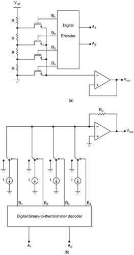 Figure 5.2: Non-SC thermometer-code DACs. (a) Resistor-string DAC. (b) Current-steering DAC.
 Generally speaking, to realize an M-bit thermometer-coded resistor-string DAC, 2 M resistors (all equal sizes) are needed. Thus, the number of resistors, the amount of power dissipation/silicon area, and the RC time constant increase exponentially with M, making this configuration unsuitable for low-power, high-speed, or small form-factor applications.
An improved resistor-string DAC that requires only 2 ( M /2+1) resistors for an M-bit resolution is reported by Holloway [14]. The reduction in the...