The Geometrical Tolerancing Desk Reference: Creating and Interpreting ISO Standard Technical Drawings

Chapter 5: Tolerance Frame

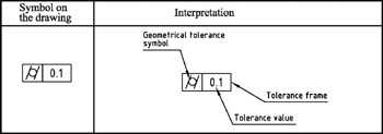
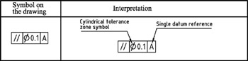
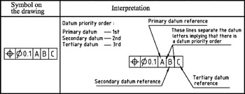
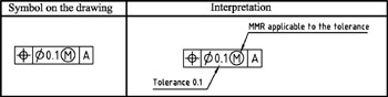
Geometrical tolerances are placed in a rectangular frame in various forms as shown below:

Example 1: Without datum
Example 2: With datum
Example 3: With multiple datum references
Example 4: With MMR (maximum material requirement) applicable to the tolerance
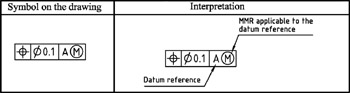
Example 5: With MMR applicable to the datum reference
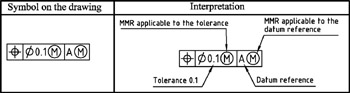
Example 6: With MMR applicable to both the tolerance and the datum reference
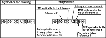
Example 7: With MMR applicable to the tolerance and more than one datum reference
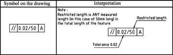
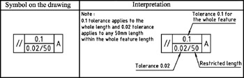
Example 8: When the tolerance is restricted to a length of a feature
Example 9: When the tolerance is restricted to the whole feature and a length of the feature
Example 10: With MMR applicable to the tolerance and more than one datum reference (the sequence of either datum is of no importance)
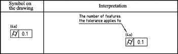
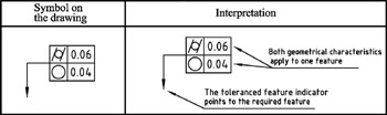
Example 11: When the tolerance applies to more than one feature
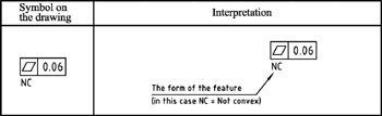
Example 12: To specify the form of the feature within the tolerance zone
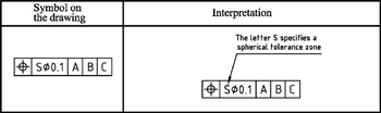
Example 13: To specify a spherical tolerance zone
Example 14: More than one tolerance frame for one feature
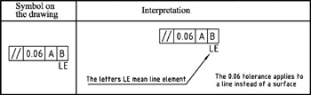
Example 15: When the form of the feature is a line instead of a surface
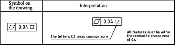
Example 16: A single tolerance zone applying to several separate features (common zone)
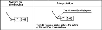
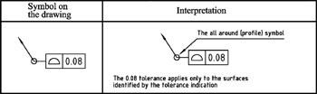
Example 17: A profile characteristic applying to the entire outline of the cross-sections
Example 18: A profile characteristic applying to the entire surface

UNLIMITED FREE
ACCESS
TO THE WORLD'S BEST IDEAS

SUBMIT
Already a GlobalSpec user? Log in.

This is embarrasing...

An error occurred while processing the form. Please try again in a few minutes.

Customize Your GlobalSpec Experience

Category: Form Gages and Form Gaging Systems
Finish!
Privacy Policy

This is embarrasing...

An error occurred while processing the form. Please try again in a few minutes.