The Geometrical Tolerancing Desk Reference: Creating and Interpreting ISO Standard Technical Drawings

Chapter 8: Toleranced Feature

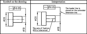
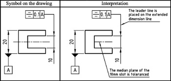
A leader line and arrowhead connects the tolerance frame to the toleranced feature. The toleranced feature is labelled in the following ways:

Example 1a: Placed on the outline of a feature
Example 1b: Placed on the outline of a feature
Example 2: Placed on the projection line
Example 3a: Placed on an extended dimension line
Example 3b: Placed on an extended dimension line
Example 4: A tolerance for a restricted part of a feature
Example 5: Placed on a reference line
Example 6: Placed on the axis
Example 7a: Placed on a common axis
Example 7b: Placed on a common axis

UNLIMITED FREE ACCESS TO THE WORLD'S BEST IDEAS

SUBMIT
Already a GlobalSpec user? Log in.

This is embarrasing...

An error occurred while processing the form. Please try again in a few minutes.

Customize Your GlobalSpec Experience

Category: Accelerometers
Finish!
Privacy Policy

This is embarrasing...

An error occurred while processing the form. Please try again in a few minutes.