The Geometrical Tolerancing Desk Reference: Creating and Interpreting ISO Standard Technical Drawings

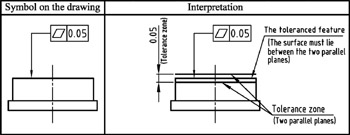
The tolerance zone is where all points of the feature are to be contained, see figure 9.1.
Figure 9.1: Example of a toleranced feature
The toleranced feature may be of any form or orientation within this zone unless restricted as shown in figure 9.2.
Figure 9.2: Example of a restricted toleranced feature
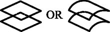
The various forms of tolerance zone are shown in table 9.1.
| Tolerance zone | Pictorial representation |
|---|---|
| Inside a circle | |
| Between two concentric circles | |
| Between two equidistant lines OR Between two parallel straight lines | |
| Inside a sphere | |
| Inside a cylinder | |
| Between two coaxial cylinders | |
| Between two parallel planes OR Between two equidistant surfaces | |
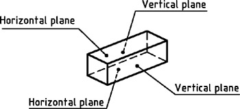
| [*] Inside a parallelepiped | |
| [*]Inside a parallelepiped is equivilent to the space between two horizontal planes and two vertical planes. |

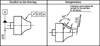
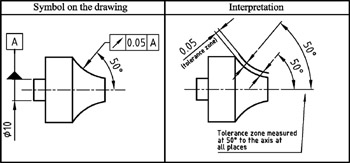
Tolerance zone width is always NORMAL to the surface (see example 1 below) unless otherwise indicated (see example 2 below).


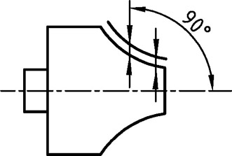
| Note | If the angle shown in example 2 above, was 90 (instead of 50 ) as in figure 9.3, it would still be shown on the drawing. This is not the same as normal to the surface as in example 1. In example 1 the 90 angle follows the contour of the surface, in example 2 the angle is always fixed in relation to the axis. |