An Analog Electronics Companion: Basic Circuit Design for Engineers and Scientists

5.1: Absolute value circuit

5.1 Absolute value circuit

If a man will begin with certainties, he shall end in doubts; but if he will be content to begin with doubts, he shall end in certainties.

Francis Bacon

The circuit is shown in Fig. 5.1.1 (Philbrick/Nexus 1968). The aim of this is to produce, from a bipolar input, an output that is the absolute value. What this means is that for a positive input the output will be positive, while for a negative input the output will also be positive. (We could also obtain the 'negative' absolute value if desired, though mathematically this is a contradiction. What is meant is that the signal is inverted.) In mathematical terms we can write:

(5.1.1)

This circuit has been chosen since it is useful in itself and also since it provides a very convenient case for a discussion of the effect of negative feedback on distortion. Here we have deliberately introduced distortion in the form of the diodes for which the form of distortion is well defined, so we know what effect it has.


Figure 5.1.1: An absolute value circuit.

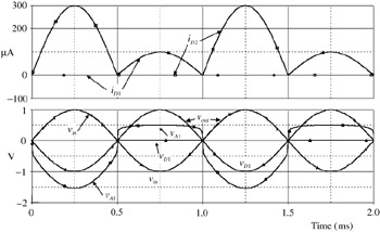
The diodes serve as polarity selectors. As noted previously, diodes have a substantially non-linear response which we might expect to lead to considerable distortion in the output signal. Typical signals are shown in Fig. 5.1.2, and it can be seen that there is no evidence of distortion in the output.


Figure 5.1.2: Waveforms for circuit of Fig. 5.1.1.

The general principle of operation is as follows. For the...

UNLIMITED FREE
ACCESS
TO THE WORLD'S BEST IDEAS

SUBMIT
Already a GlobalSpec user? Log in.

This is embarrasing...

An error occurred while processing the form. Please try again in a few minutes.

Customize Your GlobalSpec Experience

Category: High Voltage Power Supplies
Finish!
Privacy Policy

This is embarrasing...

An error occurred while processing the form. Please try again in a few minutes.