An Analog Electronics Companion: Basic Circuit Design for Engineers and Scientists
5.2: Oscilloscope probes

5.2 Oscilloscope probes

How many a man has dated a new era in his life from the reading of a book.

Henry Thoreau

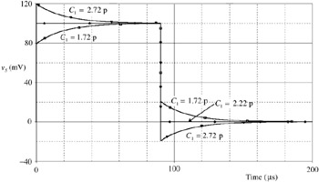
An oscilloscope probe guide (LeCroy 1994) asks whether oscilloscopes should carry a label stating 'connecting your oscilloscope probe to a circuit or device can distort the measured waveforms'. Any measurement requires interaction with the system and distorts the measurement to a greater or lesser extent. The aim is to make the disturbance as small as possible or to know how much it is disturbed and make a correction for it. Loading by the probe is usually decreased by means of a high impedance attenuator so that the improvement is bought at the expense of reduced gain. Figure 5.2.1(a) shows a 10:1 attenuator where R 2 and C 2 represent the input of the scope. A variable capacitor C 1 must be included to allow compensation so the attenuation is independent of frequency. Figure 5.2.2 shows some responses as a function of C 1.


Figure 5.2.1: ( a) Compensated attenuator. ( b) Probe schematic.

Figure 5.2.2: Response of the simple compensated attenuator of Fig. 5.2.1 ( a) with variation of C l. The three curves show under- and over-compensation as well as critical compensation, which should occur at C 1 = 20/9 = 2.22 p as observed.

In practice it is necessary to include a reasonable length of cable to allow flexibility in probing circuits and this introduces additional...

UNLIMITED FREE
ACCESS
TO THE WORLD'S BEST IDEAS

SUBMIT
Already a GlobalSpec user? Log in.

This is embarrasing...

An error occurred while processing the form. Please try again in a few minutes.

Customize Your GlobalSpec Experience

Category: IC Probing Adapters and Analysis Adapters
Finish!
Privacy Policy

This is embarrasing...

An error occurred while processing the form. Please try again in a few minutes.