An Analog Electronics Companion: Basic Circuit Design for Engineers and Scientists
Lesser artists borrow, great artists steal.
Igor Stravinsky
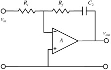
The integrator is one of the original operational circuits and formed the basis for the early analog computers or differential analysers. The basic integrator is discussed in Section 5.3. A general review of operational integrator circuits is given by Stata (1967). Here we will examine the augmenting and the non-inverting integrators. The augmenting integrator is shown in Fig. 5.5.1.
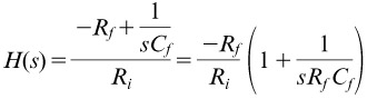
The transfer function, assuming an ideal amplifier, is:
| (5.5.1) | ![]() |
so the response is a combination of simple gain and integration. Such a circuit is useful in the control of closed-loop servo systems which require both proportional and integral terms.
Using the non-inverting operational amplifier configuration does not lead to a non-inverting integrator, but addition of an input RC as shown in Fig. 5.5.2 corrects the transfer function. The transfer function is now:
| (5.5.2) | ![]() |
when R 1 = R 2 = R and C 1= C 2 = C
which can be seen to be an integrator by comparison with Eq. (5.3.19).
A 'five decade integrator' is described in the datasheet for the CLC428 dual wideband low-noise voltage feedback amplifier (National Semiconductor 1997; Smith 1999). The circuit makes use of both amplifiers to give very high gain which results in an integrator response over a very wide bandwidth. There is of course a considerable problem in ensuring stability, both dynamic and of offset, with such high gain. The resistors R