Circuit Analysis II with MATLAB Applications

Designed for use in a second course in circuit analysis, this text engages a full spectrum of circuit analysis related subjects ranging from the most abstract to the most practical.
 TABLE OF CONTENTS
 The total response of a series RLC circuit, which is excited by a sinusoidal source, will also consist of the natural and forced response components. As we found in the previous section, the natural response can be overdamped, or critically damped, or underdamped. The forced component will be a sinusoid of the same frequency as that of the excitation, and since it represents the AC steady-state condition, we can use phasor analysis to find it. The following example illustrates the procedure.
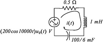
For the circuit of Figure 1.8, i L( 0) = 5 A, v C( 0) = 2.5 V, and the 0.5 ? resistor represents the resistance of the inductor. Compute and sketch i( t) for t > 0.
Solution:
This circuit is the same as that of Example 1.1 except that the circuit is excited by a sinusoidal source; therefore it can be represented by the integrodifferential equation

whose solution consists of the summation of the natural and forced responses. We know its natural response from the previous example. We start with

where the constants k 1 and k 2 will be evaluated from the initial conditions after i f( t) has been found. The steady state (or forced) response will have the form i f( t) = k 3cos( 10, 000t + ?