Circuit Analysis II with MATLAB Applications

Designed for use in a second course in circuit analysis, this text engages a full spectrum of circuit analysis related subjects ranging from the most abstract to the most practical.
This chapter presents applications of the Laplace transform. Several examples are given to illustrate how the Laplace transformation is applied to circuit analysis. Complex impedance, complex admittance, and transfer functions are also defined.
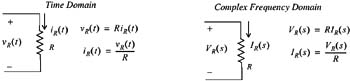
In this section we will derive the voltage-current relationships for the three elementary circuit devices, i.e., resistors, inductors, and capacitors in the complex frequency domain.
The time and complex frequency domains for purely resistive circuits are shown in Figure 6.1.
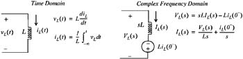
The time and complex frequency domains for purely inductive circuits is shown in Figure 6.2.
The time and complex frequency domains for purely capacitive circuits is shown in Figure 6.3.
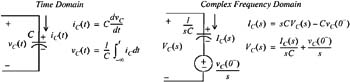
| Note | In the complex frequency domain, the terms sL and 1 /sC are called complex inductive impedance, and complex capacitive impedance respectively. Likewise, the terms and sC and 1 /sL are called complex capacitive admittance and complex inductive admittance respectively. |
Use the Laplace transform method to find the voltage v C( t) across the capacitor for the circuit of Figure 6.4, given that v C( 0 ?) = 6 V.
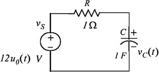
Solution:
We apply KCL at node A as...