Circuit Analysis II with MATLAB Applications

Designed for use in a second course in circuit analysis, this text engages a full spectrum of circuit analysis related subjects ranging from the most abstract to the most practical.
This chapter defines series and parallel resonance. The quality factor Q is then defined in terms of the series and parallel resonant frequencies. The half-power frequencies and bandwidth are also defined in terms of the resonant frequency.
Consider phasor series RLC circuit of Figure 2.1.
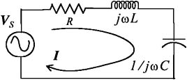
The impedance Z is
or
Therefore, the magnitude and phase angle of the impedance are:
and
The components of Z are shown on the plot of Figure 2.2.
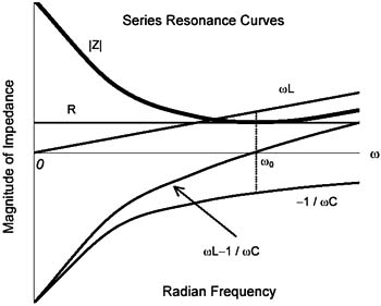
The frequency at which the capacitive reactance X C = 1 / ? C and the inductive reactance X L = ? L are equal is called the resonant frequency. The resonant frequency is denoted as ? 0 or f 0 and these can be expressed in terms of the inductance L and capacitance C by equating the reactances, that is,
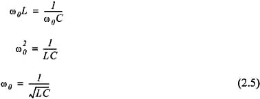
and
We observe that at resonance Z 0 = R where Z 0 denotes the impedance value at resonance, and ? Z = 0. In our subsequent discussion the subscript zero will be used to indicate that the circuit variables are at resonance.
For the circuit shown in Figure 2.3, compute I 0, ? 0, C, V R0, V L0, and V C0. Then, draw a...