Circuit Analysis II with MATLAB Applications

Designed for use in a second course in circuit analysis, this text engages a full spectrum of circuit analysis related subjects ranging from the most abstract to the most practical.
This chapter begins with the general principles of one and two-port networks. The z, y, h, and g parameters are defined. Several examples are presented to illustrate their use. It concludes with a discussion on reciprocal and symmetrical networks.
Generally, a network has two pairs of terminals; one pair is denoted as the input terminals, and the other as the output terminals. Such networks are very useful in the design of electronic systems, transmission and distribution systems, automatic control systems, communications systems, and others where electric energy or a signal enters the input terminals, it is modified by the network, and it exits through the output terminals.
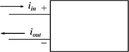
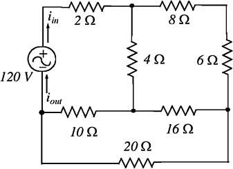
A port is a pair of terminals in a network at which electric energy or a signal may enter or leave the network. A network that has only one pair a terminals is called a one-port network. In an one-port network, the current that enters one terminal must exit the network through the other terminal. Thus, in Figure 9.1, i in = i out
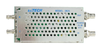
Figures 9.2 and 9.3 show two examples of practical one-port networks.
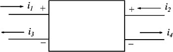
A two-port network has two pairs of terminals, that is, four terminals as shown in Figure 9.4 where i 1 = i 3 and i 2 = i 4