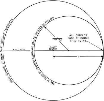
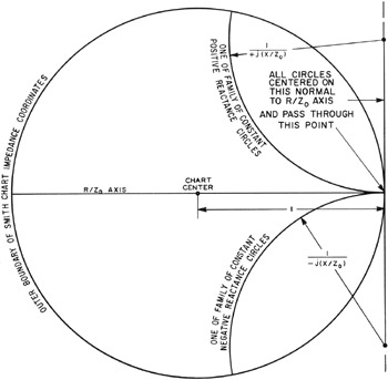
Electronic Applications of the Smith Chart: In Waveguide, Circuit, and Component Analysis

This chapter describes the construction of the basic coordinates of the SMITH CHART (Fig. 2.3) and then discusses some of the more important waveguide electrical parameters related thereto. All of these related parameters may be graphically portrayed as either radial or peripheral scales.
The construction of the basic series impedance or parallel admittance coordinates of the SMITH CHART is shown in Figs. 3.1 and 3.2. Figure 3.1 applies to the normalized resistance circles R/Z 0, while Fig. 3.2 applies to the superimposed normalized reactance circles jX/Z 0. The same construction is applicable to the basic admittance coordinates, by substituting G/Y 0 for R/Z 0 in Fig. 3.1, and by substituting +jB/Y 0 for +jX/Z 0 (and - jB/Yo for - jX/Z 0) in Fig. 3.2.
The impedance or admittance coordinates of the SMITH CHART would be of little use were it not for the accompanying related peripheral and radial scales which have general application to waveguide propagation problems, and which serve as the entry and exit to the chart coordinates. Peripheral scales generally haveto do with chart coordinate quantities which vary with position along the waveguide, while radial scales have to do with chart coordinate quantities which vary with reflection and attenuation characteristics of the waveguide.
Two...