Handbook of Mechanical Engineering Calculations, Second Edition

Section 20: Gear Design and Application

ANALYZING GEARS FOR DYNAMIC LOADS

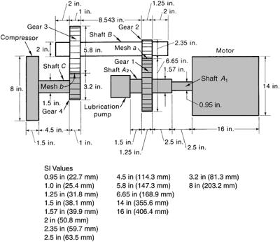
A two-stage, step-up gearbox drives a compressor and has a lubrication pump mounted on one of the gear shafts, Fig. 1. Tables 1, 2, and 3 show the spur-gear data, tolerances for tooth errors, and polar moments of inertia for the masses in the compressor drive. All gears in the drive have 20 pressure angles. The gears are made of steel; the compressor is made of cast iron. A 50-hp (37.3-kW) motor drives the gearbox at 3550 rpm. What are the dynamic loads on this gearbox?


Figure 1: Two-stage step-up gearbox driving a compressor ( Machine Design.)
Table 1: Spur Gear Data

Number of teeth, N

Pitch radius Face width

Lewis form factor, y

R (in)

mm

F (in)

mm

Gear 1

133

3.325

84.5

1.25

31.8

0.276

Gear 2

47

1.175

29.8

1.25

31.8

0.256

Gear 3

116

2.90

73.7

1.00

25.4

0.275

Gear 4

64

1.60

40.6

1.00

25.4

0.264

Table 2: Tolerances for Tooth Errors

Tolerance for tooth profile error e p

Tolerance for tooth spacing error e s

in mm in mm

Gear 1

0.0010

0.0254

0.0007

0.0178

Gear 2

0.0009

0.0229

0.00065

0.0165

Gear 3

0.0010

0.0254

0.0007

0.0178

Gear 4

0.0009

0.0229

0.00065

0.0165

Table 3: Polar Moment of Inertia of Cylindrical Masses

Diameter, D

Length, L

Polar moment of inertia, I o

Element in mm in mm

in 2 lb s 2/ft

UNLIMITED FREE
ACCESS
TO THE WORLD'S BEST IDEAS

SUBMIT
Already a GlobalSpec user? Log in.

This is embarrasing...

An error occurred while processing the form. Please try again in a few minutes.

Customize Your GlobalSpec Experience

Category: Spur Gears
Finish!
Privacy Policy

This is embarrasing...

An error occurred while processing the form. Please try again in a few minutes.