Integrated Circuit Design for High-Speed Frequency Synthesis

A major challenge in most oscillator designs is to meet the phase noise requirements of the system. An ideal oscillator has a frequency response that is a simple impulse at the frequency of oscillation. However, real oscillators exhibit "skirts" caused by instantaneous jitter in the phase of the waveform. Noise that causes variations in the phase of the signal (distinct from noise that causes fluctuations in the amplitude of the signal) is referred to as phase noise. The waveform of a real oscillator can be written as
| (8.47) | |
where ? n( t) is the phase noise of the oscillator. Here, amplitude noise is ignored because it is usually of little importance in most system specifications. Because of amplitude limiting in integrated oscillators, typically AM noise is lower than FM noise. There are several major sources of phase noise in an oscillator, and they will be discussed next.
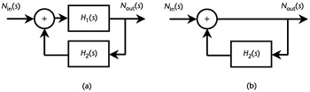
In order to derive a formula for phase noise in an oscillator, we will start with the feedback model of an oscillator as shown in Figure 8.32. For the purpose of this analysis, we will assume that H 1 is equal to one; hence, we can use the circuit shown in Figure 8.32(b).
From control theory, it is known that
| (8.48) |