An Introduction to Mixed-Signal IC Test and Measurement

This text encompasses the testing of both analog and mixed-signal circuits, value-added benefits of testing to a manufacturer s product, as well as the role of the test engineer.
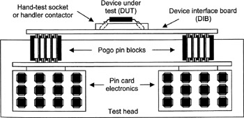
Before a test program can evaluate the quality of a device under test (DUT), the DUT must be connected to the ATE tester using a test fixture such as a device interface board (DIB). A typical interconnection scheme is shown in Figure 3.1. When packaged devices are tested, a socket or handler contactor assembly provides the contact between the DUT and the DIB. When testing a bare die on a wafer, the contact is made through the probe needles of a probe card. The tester's instruments are connected to the DIB through one or more layers of connectors such as spring-loaded pogo pins or edge connectors. The exact connection scheme varies from tester to tester, depending on the mechanical/electrical performance tradeoffs made by the ATE vendor.
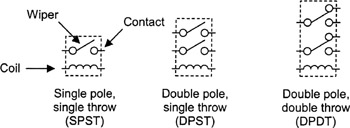
In addition to pogo pins and other connectors, electromechanical relays are often used to route signals from the tester electronics to the DUT. A relay is an electrical switch whose position is controlled by an electromagnetic field. The field is created by a current forced through a coil of wire inside the relay (Figure 3.2). Relays are used extensively in mixed-signal testing to modify the electrical connections to and from the DUT as the test program progresses from test to test.
Any of the electrical connections between a DUT and the tester can be defective, resulting in open circuits or shorts between electrical signals. For...