An Introduction to Mixed-Signal IC Test and Measurement

This text encompasses the testing of both analog and mixed-signal circuits, value-added benefits of testing to a manufacturer s product, as well as the role of the test engineer.
The transfer function (frequency response) of a filter or other analog channel is defined not only by the gain variations over frequency (magnitude response) but also by the phase shift variations (phase response). In analog and mixed-signal testing, the frequency response test often measures only the magnitude response of a circuit. The phase information contained in the FFT results is frequently discarded because phase response is often an unspecified parameter. If phase response is specified in the data sheet, however, it can be calculated using the FFT results collected during the frequency response test.
Assuming that the tester's FFT routine returns the complex coefficients of the discrete-time Fourier series in the form of a vector X, then according to the development in Chapter 7, the amplitude of the kth tone is calculated according to
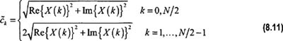
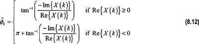
where Re{ X( k)} and Im{ X( k)} denote the real and imaginary parts of the kth element of vector X. Correspondingly, the phase shift of the kth tone can be calculated using the formula
To aid the user, most testers include a DSP routine to convert the results of an FFT into polar notation (magnitude and phase). The polar conversion routines perform whatever corrections are necessary to compute a correct phase shift. Although the built-in polar conversion approach is easier than doing the conversion manually, it can be less efficient. Why should we calculate the magnitude and phases of all...