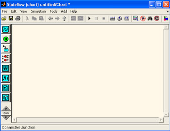
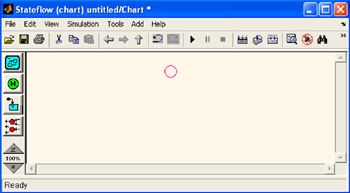
Introduction to Stateflow with Applications

This chapter describes the use of connective junctions to represent a decision point between alternate transition paths for a single transition. Flow diagram notation uses connective junctions to represent common code structures such as for loops and if then else constructs without the use of states.
Figure 6.1 is our familiar Stateflow Editor window, and when we place the mouse cursor over the Connective Junction tool
, its name appears at the bottom of the window.
To create a connective junction, we do the following:
In the diagram toolbar, we click the Connective Junction tool ![]()
We move the cursor into the diagram editor.The cursor takes on the shape of a connective junction as shown in Figure 6.2. We click to place a connective junction in the desired location in the drawing area.
To create multiple connective junctions, we do the following:
In the diagram toolbar, we double click the Connective Junction tool
and the connective junction is now in multiple object mode.
We click anywhere in the drawing area to place a connective junction in the drawing area. We move to and click another location to create an additional connective junction. We click the Connective Junction tool or we press the Esc key to terminate the operation. To move a connective junction to a new...