Iterative Receiver Design

Exploiting the power of factor graphs, this detailed text provides a general framework for systematically developing iterative algorithms for digital receivers, and highlights connections between important algorithms.
 TABLE OF CONTENTS
 We have two goals in this chapter: first of all, we will replace the node p( C B,  ) in Fig. 8.1 by a more detailed factor graph depending on the particular type of error-correcting code. Secondly, we will show how the SPA can be executed on the resulting factor graphs. For every type of code, we will draw the factor graph, locate the basic building blocks in the graph, and show how to implement the SPA on these blocks. We will end by deriving the decoding algorithms in the probability domain, the log-domain, and the LLR domain. We remind the reader that these message types were discussed in Section 5.3.3.
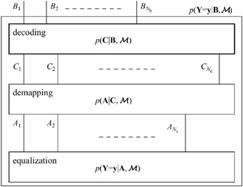 ). The node is opened to reveal its structure. The node in bold is the topic of this chapter.
To help the reader understand the decoding algorithms, one can imagine the coded bits being mapped to BPSK symbols, such that a k = 2 c k ? 1, k = 1, , N c, and that y k = a k + n k, where n k ~  (0, ? 2). In that case,
  and
and  . Hence, the upward messages on the C k-edges in Fig. 8.1 are given by
  . Here, the subscript dec stands for the decoding node. From the previous chapter we know that the downward messages on the B