Microwave Radio Transmission Design Guide
A practical guide for engineers planning or building a microwave-based transmission system, with a special eye toward international standards.
 TABLE OF CONTENTS
 Link design is mainly about accurately predicting the outage period that a radio link will suffer and ensuring that it does not exceed the quality objectives discussed in Chapter 3. Most outages occur as a result of atmospheric effects; therefore, it is necessary for the radio planner to have a thorough understanding of microwave propagation.
Many articles written about radio links imply that the beam is a pencil-thin ray that travels in a straight line between two antennas. In reality, it is an electromagnetic wavefront that is infinitely wide even with high-gain microwave antennas. The path that the wavefront travels is dependent on the density of the troposphere the lower portion of the atmosphere that it encounters. In a vacuum the density that the wavefront would encounter is uniform. In a so-called standard atmosphere the average density decreases with altitude. The upper portion of the wavefront thus travels faster than the lower portion that is traversing the denser medium. Since the direction of propagation of an electromagnetic wavefront is always perpendicular to the plane of constant phase, the beam bends downward. This is called refraction.
The refractive index ( n) is the ratio of the speed of an electromagnetic wave traveling in a vacuum relative to the speed it would travel in a finite medium as expressed by
| (5.1) | 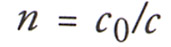 |